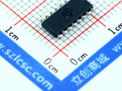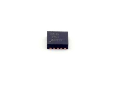
In this article, we explore the common troubleshooting issues and solutions for the 10M08SCU324C8G FPGA , offering valuable insights for engineers and technicians working with this popular device. From configuration errors to Power issues, we provide practical advice to help you resolve the most frequent challenges encountered during development and deployment.
10M08SCU324C8G, FPGA troubleshooting, FPGA solutions, configuration errors, power issues, design tips, Altera, hardware debugging, common problems, troubleshooting guide.
Understanding the Common Problems with 10M08SCU324C8G FPGA
The 10M08SCU324C8G is a versatile FPGA from Intel (formerly Altera), widely used for embedded system designs, industrial control, communications, and data processing. Despite its powerful capabilities and flexibility, engineers often encounter a variety of issues when working with this device. Understanding these challenges is the first step to resolving them efficiently. In this section, we will discuss the most common problems and how to address them.
1. Configuration Failures
Configuration is one of the most crucial steps when working with FPGAs. The 10M08SCU324C8G supports various configuration modes, such as JTAG, active serial, and passive serial. One of the most common issues developers face is a failed configuration. Here are some common causes and solutions:
Causes:
Incorrect configuration file: The FPGA might fail to load if the bitstream is not generated correctly or is incompatible with the device.
Corrupted memory or flash storage: If the configuration data stored in the external memory is corrupted, the FPGA will not be able to configure itself on power-up.
Power supply issues: Insufficient or unstable power supply can cause the FPGA to malfunction during configuration.
Solutions:
Verify the bitstream: Ensure that the bitstream (.sof file) is correctly compiled for the 10M08SCU324C8G using Intel’s Quartus software. Double-check the target device settings during the compilation.
Check memory integrity: If you are using an external flash memory for configuration, ensure it is functioning properly. Perform a read-write test or try re-flashing the memory.
Stable power supply: Use a regulated power supply that meets the FPGA’s voltage requirements. Instabilities or under-voltage conditions can lead to partial or failed configuration.
2. Power Supply Problems
Power-related issues are one of the most frequent problems in FPGA designs. The 10M08SCU324C8G operates at 1.2V, and ensuring that the voltage levels are correct is critical for stable operation.
Causes:
Inadequate power decoupling: FPGAs require stable and clean power for proper operation. If power decoupling capacitor s are missing or improperly placed, the device might experience noise or voltage dips.
Power sequencing issues: Power supplies must be applied in a specific sequence, especially when dealing with external devices like DDR memory or high-speed peripherals.
Power spikes or drops: Sudden voltage fluctuations can disrupt normal FPGA operation and cause resets or failures.
Solutions:
Proper decoupling capacitors: Ensure that sufficient decoupling capacitors (typically 0.1µF to 10µF) are placed close to the power pins of the FPGA. This helps to filter out noise and voltage transients.
Follow power-up sequence: Follow the recommended power-up sequence as per the 10M08SCU324C8G datasheet. This is especially important when using external devices like DDR SDRAM.
Monitor power quality: Use an oscilloscope to monitor the power rails and check for voltage spikes or dips during operation.
3. Signal Integrity Issues
Signal integrity is critical when designing FPGA-based systems, especially when dealing with high-speed communication interface s. Poor signal integrity can lead to unexpected behavior, Timing failures, and even permanent damage to the device.
Causes:
Long trace lengths: Excessively long PCB traces can lead to signal degradation, resulting in unreliable communication.
Improper grounding: An inadequate ground plane or poor grounding techniques can introduce noise into the system, causing errors or glitches.
Insufficient termination: Signal lines not terminated correctly can cause reflections, which result in signal distortion.
Solutions:
Minimize trace lengths: Keep PCB trace lengths as short as possible, especially for high-speed signals like Clock lines, data buses, and serial communication signals.
Use proper grounding techniques: Implement a solid ground plane and ensure that ground connections are low-impedance to reduce noise and signal interference.
Use termination resistors: Use appropriate termination resistors on high-speed signal lines to prevent reflections.
4. Incorrect I/O Voltage Levels
The 10M08SCU324C8G supports both 3.3V and 1.8V I/O standards, making it versatile for various applications. However, incorrect I/O voltage levels can lead to communication errors or even permanent damage to the FPGA or external devices.
Causes:
Mismatched I/O voltage levels: Connecting signals with mismatched voltage levels (e.g., 3.3V I/O to a 1.8V I/O pin) can damage the FPGA or result in incorrect logic levels.
Over-voltage or under-voltage conditions: Exposing I/O pins to voltages outside the specified range can cause malfunction or damage.
Solutions:
Verify voltage levels: Always check the I/O voltage levels on both the FPGA and external devices. Use a multimeter or oscilloscope to confirm that the voltage levels match the requirements.
Use level shifters: If the FPGA is interfacing with devices that use different voltage levels, use level shifters to ensure compatibility.
Advanced Troubleshooting and Solutions for the 10M08SCU324C8G FPGA
In this part of the article, we delve into more advanced troubleshooting techniques and solutions for resolving issues with the 10M08SCU324C8G FPGA. While many problems can be addressed with basic checks, some issues require more in-depth debugging and analysis.
5. Clocking and Timing Issues
FPGAs like the 10M08SCU324C8G rely heavily on accurate clock signals for synchronous operation. Timing issues are common when multiple clock domains are used or when clocks are not properly constrained.
Causes:
Clock skew: When clock signals are distributed over long distances or through multiple stages of logic, delays (clock skew) can accumulate and cause timing violations.
Improper clock constraints: Failing to properly constrain clocks in the design can lead to timing errors during synthesis or simulation, causing setup or hold violations.
Incorrect PLL configurations: If Phase-Locked Loops ( PLLs ) or clock dividers are misconfigured, they can introduce instability in clock generation.
Solutions:
Minimize clock skew: Place clock distribution components as close to the FPGA as possible. Use buffers or clock drivers to reduce the delay in the clock signal path.
Set correct clock constraints: Ensure that the clock constraints are correctly defined in the Quartus project. Use the timing analyzer to verify that there are no violations.
Double-check PLL settings: Review the PLL configuration to ensure that it matches the requirements of the design, and make sure that the input clock is stable and within the required frequency range.
6. Inconsistent Behavior During Debugging
Debugging FPGAs often requires using tools like the JTAG interface, in-system logic analyzers, or hardware breakpoints. However, inconsistent behavior during debugging can lead to confusion and wasted time.
Causes:
Incorrect debug configurations: If the debugging tools or settings are not properly configured, they might not capture or display relevant signals, making the debugging process ineffective.
Inadequate signal capture: When debugging high-speed signals or large designs, the in-system debugger may not capture the entire signal range, leading to gaps in data.
Timing mismatches: Timing mismatches between the testbench and the real hardware setup can lead to incorrect debug results.
Solutions:
Check debug settings: Ensure that the correct pins and signals are being monitored during debugging. Configure the debugger or logic analyzer to capture only relevant data.
Increase signal capture depth: When using in-system logic analyzers or debugging tools, increase the capture depth or sample rate to ensure you capture all the necessary data.
Sync with testbenches: Make sure your simulation and hardware setups are synchronized in terms of timing and signal expectations.
7. Thermal Management and Overheating
Thermal management is often overlooked, but excessive heat can cause unpredictable behavior or even permanent damage to the FPGA. The 10M08SCU324C8G, like all FPGAs, requires effective thermal management to maintain stable operation.
Causes:
Inadequate cooling: Insufficient heat sinking or airflow around the FPGA can cause it to overheat, especially when running at high utilization.
High power consumption: Complex designs or high-speed operations may increase the power consumption of the FPGA, resulting in higher heat output.
Solutions:
Use heat sinks or cooling fans: Install heat sinks or fans near the FPGA to dissipate heat effectively.
Optimize design for power efficiency: Reduce the FPGA’s power consumption by optimizing the design for lower utilization and reducing unnecessary logic operations.
Monitor temperature: Use temperature sensors or thermal cameras to monitor the FPGA’s temperature during operation.
8. Firmware and Software Compatibility Issues
Sometimes, the problem isn’t hardware-related but software-related. Compatibility between the FPGA firmware (bitstream) and the host software can cause issues such as crashes, erratic behavior, or data corruption.
Causes:
Incompatible software versions: Using an outdated or incompatible version of Quartus or other development tools can cause issues during configuration, debugging, or simulation.
Misconfigured software settings: Incorrect software settings for communication interfaces (such as JTAG) or clock sources can lead to errors during operation.
Solutions:
Update development tools: Always use the latest versions of Quartus and related development software. Regularly check for software patches or updates.
Review software configurations: Double-check the software settings to ensure compatibility with the hardware configuration. Verify that all clock sources and interfaces are correctly specified.
By addressing these common issues, you can ensure that your development with the 10M08SCU324C8G FPGA is smooth and successful. Troubleshooting FPGAs requires patience and attention to detail, but with the right approach, most problems can be resolved efficiently, leading to optimal system performance.
If you are looking for more information on commonly used Electronic Components Models or about Electronic Components Product Catalog datasheets, compile all purchasing and CAD information into one place.
Partnering with an electronic components supplier sets your team up for success, ensuring the design, production, and procurement processes are quality and error-free.


