This article delves into the practical application of the MC33063ADR 2G integrated circuit (IC) in simple DC-DC conversion circuits. It explores its functionalities, benefits, and real-world uses for efficient voltage conversion in electronic designs. The article will provide a detai LED analysis of how to implement the MC33063AD R2G in various configurations, offering insights into its versatility and performance in Power supply systems.
MC33063ADR2G , DC-DC conversion, voltage regulation, power supply design, integrated circuits, electronics, switching regulators, energy efficiency
Understanding the MC33063ADR2G and Its Role in DC-DC Conversion
The MC33063ADR2G is an integrated circuit (IC) designed to facilitate efficient DC-DC conversion. It serves as a versatile and reliable solution for creating compact, low-power, and cost-effective switching power supplies. Whether you are an experienced electronics engineer or a beginner exploring the world of power supplies, understanding how the MC33063ADR2G functions can open the door to innovative and efficient circuit designs.
What is DC-DC Conversion?
Before diving into the specifics of the MC33063ADR2G, it’s essential to understand what DC-DC conversion is and why it plays such a pivotal role in modern electronic systems. DC-DC conversion refers to the process of changing a source voltage from one level to another. For example, converting a 12V battery output to a stable 5V or 3.3V needed for powering microcontrollers or sensors.
This is achieved through switching regulators, which are much more efficient than linear regulators. DC-DC converters can step up (boost) or step down (buck) the voltage depending on the design requirements, making them an integral component in a wide range of applications, from portable electronics to industrial equipment.
The Role of the MC33063ADR2G in DC-DC Conversion
The MC33063ADR2G is a monolithic IC capable of both step-up (boost) and step-down (buck) voltage conversion. It’s specifically designed to be used in low-power, cost-sensitive applications where efficiency and size are important factors. The MC33063ADR2G integrates the necessary components to operate a DC-DC converter in one package, reducing the need for additional external components, which can save both board space and cost.
Key features of the MC33063ADR2G include:
Wide input voltage range: It can operate with input voltages from 3V to 40V.
Output voltage regulation: It can provide stable output voltages, which can be adjusted depending on the requirements of the load.
High efficiency: The IC’s switching design ensures that energy loss is minimized, leading to improved system performance and lower heat dissipation.
Multiple configurations: The MC33063ADR2G can be configured as a boost converter, buck converter, or inverting regulator, offering a lot of versatility for various use cases.
This flexibility makes the MC33063ADR2G an excellent choice for projects such as battery-powered devices, power adapters, and low-voltage systems requiring high-efficiency power conversion.
Key Features and Advantages
Integrated Design: The MC33063ADR2G is an all-in-one solution for DC-DC conversion, with built-in components such as a switching transistor , error amplifier, and voltage reference. This integration simplifies the design process and minimizes external components, making it ideal for compact circuits.
Efficiency: One of the most significant advantages of using a DC-DC converter like the MC33063ADR2G is its high efficiency compared to linear regulators. In linear regulators, excess voltage is dissipated as heat, while in switching regulators, energy is transferred more efficiently, resulting in less heat generation.
Cost-Effective: Since the MC33063ADR2G combines multiple functions into a single IC, it reduces both component count and overall system cost. Additionally, the IC’s ability to operate in various configurations (buck, boost, and inverting) makes it a versatile solution for different design needs.
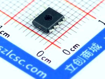
Compact Size: The MC33063ADR2G is available in compact packages, which is a critical consideration for space-constrained designs. Whether you’re working on a small portable device or a larger system, the IC’s small footprint allows it to fit seamlessly into your layout.
Practical Applications
The MC33063ADR2G can be found in a variety of applications that require efficient power conversion. Here are some practical uses:
Battery-Powered Devices: The MC33063ADR2G can step down voltage from a higher battery voltage to a stable lower voltage to power microcontrollers, sensors, and other low-voltage components in portable devices like handheld gadgets and IoT devices.
Power Adapters: It can also be used in AC-to-DC converters to provide stable output voltages for powering electronic equipment.
Automotive Electronics: In vehicles, the MC33063ADR2G can be used to regulate voltage from the car’s 12V power system to provide lower voltages for internal circuits like LED lighting, sensors, and onboard communication systems.
Key Circuit Design Considerations
When designing a DC-DC conversion circuit with the MC33063ADR2G, there are several important factors to consider to ensure the best performance:
Inductor Selection: The efficiency and performance of the DC-DC converter heavily depend on the choice of inductor. The MC33063ADR2G requires an external inductor, and its value should be selected based on the operating frequency and load current.
capacitor s: Both input and output Capacitors are essential for maintaining voltage stability and minimizing noise in the circuit. The MC33063ADR2G typically requires small ceramic capacitors, which offer low ESR (Equivalent Series Resistance ) and good filtering capabilities.
Feedback Loop: Proper feedback is essential for maintaining a stable output voltage. The MC33063ADR2G uses an internal feedback mechanism that adjusts the duty cycle of the switching transistor to regulate the output voltage. External components, like Resistors , are often used to set the feedback voltage level.
Switching Frequency: The IC’s internal switching frequency is typically around 100kHz, which is a good balance between efficiency and size of the passive components. However, some designs may use a different frequency, depending on the specific requirements of the application.
Real-World Case Study of MC33063ADR2G Implementation in a DC-DC Conversion Circuit
In this section, we will walk through a case study where the MC33063ADR2G is used to design a step-down (buck) converter circuit, ideal for powering a low-voltage device from a higher-voltage source, such as stepping down from 12V to 5V. This example demonstrates the practical steps involved in setting up the circuit, selecting components, and optimizing performance.
Step-by-Step Design Process
Choosing the Input and Output Parameters
For this example, let’s assume the goal is to step down a 12V input to a stable 5V output. The target current for the load is 1A. These specifications will guide the selection of external components like the inductor, capacitors, and resistors.
Inductor Selection
The MC33063ADR2G requires an external inductor for energy storage during the switching cycle. A typical value for the inductor in a 12V-to-5V buck converter might range from 100µH to 470µH, depending on the specific design. For this case, we’ll select a 220µH inductor that offers a good balance between efficiency and size. The inductor should also have a current rating high enough to handle the peak current without saturating.
Capacitors
To ensure smooth operation and voltage stability, both input and output capacitors are needed. For the input, a 10µF ceramic capacitor helps filter high-frequency noise, while a 100µF electrolytic capacitor can be used to stabilize the input voltage. At the output, a 100µF ceramic capacitor is sufficient to smooth the voltage and reduce ripple.
Resistors for Feedback Voltage
The feedback voltage must be set to the reference voltage of the MC33063ADR2G. For a 5V output, you will need to use a resistive voltage divider. Typically, this involves selecting two resistors—one connected between the output and the feedback pin, and the other between the feedback pin and ground. The resistors’ values are chosen based on the formula:
[
V{\text{out}} = V{\text{ref}} \times \left(1 + \frac{R1}{R2}\right)
]
Where (V{\text{ref}}) is the reference voltage (typically 1.25V) and (V{\text{out}}) is the desired output voltage. For a 5V output, a typical choice for (R1) and (R2) would be 3.3kΩ and 1.5kΩ, respectively.
Testing and Optimization
Once the components are selected and the circuit is assembled, it’s important to test the converter under load conditions to ensure the output is stable and the IC is not overheating. You can use an oscilloscope to measure ripple on the output voltage and fine-tune the feedback loop if necessary.
Real-World Considerations
In real-world applications, the MC33063ADR2G can operate efficiently under varying load conditions, but the performance may degrade if the input voltage drops too low or the output current exceeds the specified limits. Additionally, thermal management should be considered if the circuit operates at high power levels.
Conclusion
The MC33063ADR2G is an outstanding choice for designing simple, reliable, and efficient DC-DC converters. By offering both step-up and step-down conversion in a single IC, it simplifies the design process and reduces component count. Whether you are designing a power supply for a portable device or a power adapter for electronics, the MC33063ADR2G provides a cost-effective solution that doesn’t sacrifice performance.
Partnering with an electronic components supplier sets your team up for success, ensuring the design, production, and procurement processes are quality and error-free.