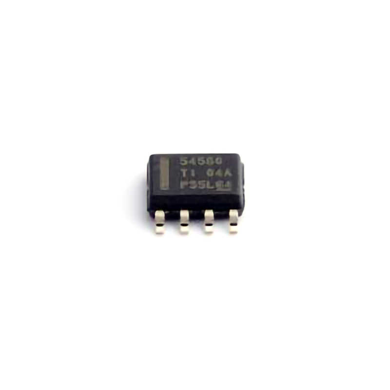
Identifying Common Issues with the TPS54560DDAR
The TPS54560DDAR is a highly efficient, integrated step-down regulator, capable of converting a wide input voltage range (4.5V to 60V) into a stable output. While its reliability and flexibility make it a popular choice in Power supply designs, engineers and designers sometimes encounter issues that can affect its performance. In this section, we will walk through some of the most common problems with the TPS54560DDAR and explore potential causes for these issues.
1. No Output Voltage or Low Output Voltage
One of the most frequent issues faced by engineers when working with the TPS54560DDAR is the complete absence of output voltage or an output that is lower than expected. There are several potential causes for this behavior:
a. Insufficient Input Voltage:
The TPS54560DDAR requires a minimum input voltage of 4.5V to operate. If the input voltage drops below this threshold, the regulator will not be able to generate the required output. Make sure that the input voltage is within the recommended operating range (4.5V to 60V) and that there are no significant voltage drops due to cable Resistance or power supply instability.
b. Faulty External Components:
External components like inductors, Capacitors , and resistors play a significant role in the functionality of the TPS54560DDAR. A short-circuited or open circuit in any of these components could lead to a lack of output voltage. For example, an incorrect inductor value or a damaged output capacitor could disrupt the voltage regulation process. Always verify the correct values and quality of the external components.
c. Overcurrent Protection:
The TPS54560DDAR has built-in overcurrent protection. If the load requires more current than the regulator can supply, the device will enter a fault state, causing the output to drop to zero or a very low voltage. In this case, check the load conditions and ensure that the current demand does not exceed the maximum rating.
2. Output Voltage Ripple and Noise
Excessive ripple or noise on the output voltage can be problematic in applications that require clean, stable power. The TPS54560DDAR, being a switching regulator, naturally generates some ripple, but excessive noise or ripple may indicate issues with the design.
a. Poor PCB Layout:
A poor PCB layout can cause noise to couple into the output, particularly when the layout of the power and ground traces is not optimal. Ensure that the high-current paths (input and output traces) are wide and as short as possible. Keep the switching node away from sensitive analog circuitry and ensure that the ground plane is solid and uninterrupted.
b. Inadequate Output Capacitors:
The TPS54560DDAR typically requires high-quality low ESR (Equivalent Series Resistance) capacitors on the output to filter out ripple and stabilize the output voltage. Insufficient capacitance or the use of inappropriate capacitor types can lead to increased ripple. Check that the capacitors meet the recommended specifications in the datasheet.
c. Input Voltage Spikes:
Spikes on the input voltage can also cause fluctuations in the output. Ensure that the input voltage is clean and that proper filtering is implemented at the input side. Adding bulk capacitors or improving input filtering can help reduce these spikes.
3. Thermal Shutdown or Overheating
Overheating can be another issue that affects the TPS54560DDAR. This component is designed to operate within a specific temperature range, and exceeding these limits can result in thermal shutdown or degradation in performance.
a. Insufficient Heat Dissipation:
The TPS54560DDAR has an internal thermal shutdown feature that activates when the junction temperature exceeds the safe threshold. Ensure that the regulator is properly cooled, especially in designs with high current demands. Adding heat sinks or improving the PCB layout to maximize heat dissipation can help keep the temperature within the safe operating range.
b. High Power Dissipation:
The efficiency of the TPS54560DDAR is typically high, but power dissipation can still occur, especially when there is a significant difference between input and output voltages. For example, if the input voltage is much higher than the output voltage, more power is dissipated as heat. Consider optimizing the input and output voltage levels to minimize power loss and reduce the chances of overheating.
4. Incorrect Feedback or Compensation Circuitry
The TPS54560DDAR uses an external resistor divider to set the output voltage, and it requires a properly designed feedback and compensation network to maintain stable regulation.
a. Incorrect Feedback Resistor Values:
If the feedback resistors are incorrectly chosen or have drifted in value, the output voltage may deviate from the desired level. Double-check the resistor values and ensure that they are within the recommended range for your application.
b. Compensation Network Design:
A poor compensation network can cause instability in the regulator, leading to oscillations or reduced performance. The TPS54560DDAR datasheet provides guidelines for compensation network design based on the specific application requirements. Ensure that the compensation components (typically capacitors and resistors) are selected appropriately to achieve stable operation.
Advanced Troubleshooting Techniques and Solutions
While the common issues outlined in Part 1 are typically easier to address, there are situations where more advanced troubleshooting methods are required. In this section, we will dive into more in-depth troubleshooting strategies and solutions for the TPS54560DDAR, focusing on more complex problems that may arise.
5. Faulty Start-Up Behavior
Sometimes, the TPS54560DDAR may exhibit faulty start-up behavior, such as delayed start-up or failure to start altogether. This can be due to several factors, and pinpointing the issue requires careful examination of the start-up sequence.
a. Inadequate Soft-Start Capacitor:
The TPS54560DDAR has a soft-start feature that gradually ramps up the output voltage to avoid excessive inrush current. If the soft-start capacitor is either too small or missing, the start-up behavior may be erratic. Ensure that the soft-start capacitor is properly selected according to the recommendations in the datasheet.
b. Power-Good Signal Issues:
The TPS54560DDAR has a Power-Good (PG) pin that signals when the output voltage is within the expected range. If the PG pin is not functioning correctly, it may indicate that the regulator is not achieving the required output voltage. Use an oscilloscope to monitor the PG pin and verify the start-up sequence.
6. Undervoltage Lockout (UVLO) Problems
The TPS54560DDAR has a built-in undervoltage lockout (UVLO) feature to protect against low input voltages that could result in unreliable operation. If the input voltage drops too low, the UVLO feature will shut down the regulator to prevent erratic behavior.
a. UVLO Threshold Adjustments:
The UVLO threshold can be adjusted using external resistors. If the input voltage is too low for stable operation, consider adjusting the UVLO threshold by modifying the resistor divider network. Ensure that the input voltage is consistently above the UVLO threshold during operation.
b. Input Voltage Sag During Load Transients:
During sudden load transients, the input voltage may sag temporarily, triggering the UVLO feature. Adding additional bulk capacitors at the input can help stabilize the input voltage during these transients and prevent the UVLO from falsely triggering.
7. Load Regulation Issues
Load regulation refers to the ability of the TPS54560DDAR to maintain a stable output voltage as the load current changes. If the output voltage fluctuates significantly with varying load conditions, the regulator may not be functioning optimally.
a. Inadequate Output Capacitor Selection:
Load regulation problems can often be traced back to inadequate output capacitance. If the output capacitors are not sufficient to handle the load variations, the output voltage may dip or overshoot when the load changes. Increase the output capacitance or switch to capacitors with better high-frequency performance.
b. Improper Feedback Loop Compensation:
A poorly compensated feedback loop can result in sluggish response to load changes, leading to poor load regulation. As mentioned earlier, carefully select the compensation network components to ensure a fast, stable response to load transients.
8. Using the TPS54560DDAR in High-Frequency Applications
In high-frequency applications, the TPS54560DDAR may face additional challenges due to its switching characteristics. Ensuring stable operation in these cases requires careful attention to layout, components, and control loop design.
a. Switching Noise:
At higher switching frequencies, the TPS54560DDAR can generate more noise, which may interfere with sensitive analog circuits. Ensure proper shielding and ground planes are implemented to minimize noise coupling. Adding ferrite beads or low-pass filters on the input and output can also help reduce high-frequency noise.
b. Ensuring Stability at High Frequencies:
As the switching frequency increases, stability can become an issue. Make sure that the compensation network is designed to maintain stability at the target frequency. If necessary, experiment with different compensation values to achieve optimal performance.
In conclusion, while the TPS54560DDAR is a robust and reliable power management solution, understanding its potential failure points and addressing them through careful design and troubleshooting is essential for optimal performance. By following the advice in this article, engineers can overcome common and complex issues and ensure that their TPS54560DDAR-based designs operate reliably in a wide range of applications.
Partnering with an electronic components supplier sets your team up for success, ensuring the design, production, and procurement processes are quality and error-free.


