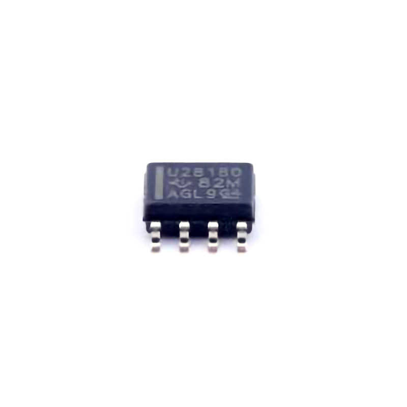
Overview of the UCC28180DR and Common Troubleshooting Issues
The UCC28180DR is a high-performance, integrated PFC controller from Texas Instruments, widely used in designing high-efficiency Power supplies that conform to stringent Power Factor Correction (PFC) requirements. This device is particularly favored for applications requiring reliable AC-to-DC conversion, such as in industrial power supplies, consumer electronics, and renewable energy systems.
However, like any complex power electronics component, it’s not immune to operational issues. Engineers and designers frequently encounter challenges during the development phase, which can lead to performance degradation or failure if not properly addressed. In this article, we will highlight some of the most common issues users face when working with the UCC28180DR and provide solutions to help mitigate them.
1.1 Understanding the UCC28180DR PFC Controller
Before diving into troubleshooting, it’s important to briefly understand the UCC28180DR’s key functionalities. It’s a current-mode, continuous-conduction-mode (CCM) PFC controller that integrates multiple features to enhance performance, such as:
High Efficiency: Designed for high-efficiency power conversion, achieving low conduction losses and low harmonic distortion.
Boost Converter Architecture: Operates as a boost converter to step up the voltage from the AC input to the desired DC output.
Power Factor Correction: Ensures that the current drawn from the AC supply is in phase with the voltage, improving efficiency and reducing the total harmonic distortion (THD).
While the UCC28180DR is a highly capable device, improper design, configuration, or faulty components can lead to operational issues. Let’s look at some of the common problems that arise in designs using this controller.
1.2 Common Troubleshooting Issues
1.2.1 Input Voltage Instability
One of the first symptoms users might notice when there’s a problem with the UCC28180DR is input voltage instability. This can manifest as fluctuating output voltage, poor regulation, or unexpected shutdowns in the power supply. Several factors can contribute to this issue:
Incorrect Input Voltage Range: If the input AC voltage exceeds or falls below the specified operating range, the controller may not be able to maintain proper output regulation.
Input capacitor Issues: A faulty or insufficient input filter capacitor can result in voltage spikes and poor input voltage stability. This can lead to high-frequency oscillations and erratic performance.
AC Mains Noise or Disturbance: Electrical noise or sudden fluctuations in the AC mains can lead to unwanted voltage dips and spikes, causing the controller to malfunction.
1.2.2 Output Voltage Regulation Problems
Another common issue with the UCC28180DR is poor output voltage regulation, which may result in overvoltage or undervoltage conditions at the output of the power supply. Here are some common causes:
Feedback Loop Instability: The feedback loop is responsible for maintaining the desired output voltage. If there is instability in the feedback path, it can cause oscillations or improper regulation.
Incorrect Sensing of Output Voltage: A wrong placement of the voltage feedback divider or improper calibration of the sense resistor can lead to inaccurate voltage regulation.
Insufficient Output Capacitors : If the output filter capacitors are too small or of poor quality, they may not filter the DC output adequately, leading to voltage ripples and instability.
1.2.3 High THD (Total Harmonic Distortion)
In many applications, minimizing THD is crucial, especially in power supplies that must comply with regulations like the IEC 61000-3-2 standard for harmonic emissions. High THD in the input current is often an indication of improper PFC operation. Common causes include:
Poor Control Loop Design: Inadequate tuning of the PFC control loop or improper compensation can result in poor current shaping and high THD.
Incorrect FET Selection: Using a MOSFET with poor switching characteristics or wrong gate drive configuration can contribute to poor PFC performance and increased harmonic distortion.
Component Mismatch: Mismatched components such as inductors, Resistors , or capacitors can lead to incorrect current sensing and a distorted input current waveform.
1.2.4 Overcurrent and Overtemperature Protection
The UCC28180DR has built-in protection features to safeguard against overcurrent and overtemperature conditions. However, false triggering of these protections can occur due to several reasons:
Incorrect Current Sense Resistor Value: The current sense resistor is used to monitor the output current. If it’s incorrectly sized or improperly placed, the controller may falsely detect an overcurrent condition.
Improper PCB Layout: A poor PCB layout with long, inductive traces can induce noise or voltage spikes that trigger the overcurrent protection mechanism.
Ambient Temperature Conditions: If the device is placed in an environment where the temperature exceeds the specified operating range, the overtemperature protection might be triggered unnecessarily.
Solutions and Best Practices for UCC28180DR Troubleshooting
Now that we’ve highlighted some of the most common issues that users may face when working with the UCC28180DR, let’s turn our attention to practical solutions and best practices for mitigating these problems.
2.1 Ensuring Proper Input Voltage Range
To avoid input voltage instability, the following measures should be taken:
Verify AC Input Voltage Range: Always ensure that the input voltage is within the specified range for the UCC28180DR, typically between 90V and 265V AC. Consider using a voltage monitor or over-voltage protection circuitry to protect against unexpected spikes or dips.
Add Input Filtering: Incorporate high-quality input capacitors to filter out high-frequency noise and smooth the input voltage. Using a combination of electrolytic and ceramic capacitors in parallel can improve filtering performance.
Isolate from Mains Noise: Use common-mode chokes or EMI filters to reduce the effects of electrical noise from the mains.
2.2 Improving Output Voltage Regulation
To maintain tight output voltage regulation, consider the following steps:
Tune the Feedback Loop: The feedback loop must be properly compensated to avoid oscillations and ensure stability. Use the appropriate compensation network as suggested in the UCC28180DR datasheet to stabilize the loop.
Correct Feedback Resistor Selection: Choose feedback resistors with tight tolerances to ensure accurate sensing of the output voltage. Properly placing the feedback voltage divider at the output node is also crucial.
Increase Output Filtering: To reduce voltage ripple, use sufficiently large output capacitors with low ESR (Equivalent Series Resistance ) ratings. Multiple capacitors with different values can provide better filtering across a wide range of frequencies.
2.3 Reducing Total Harmonic Distortion
For reducing THD, focus on the following aspects:
Optimize Control Loop Parameters: Use the recommended control loop design guidelines and properly compensate the system for best performance. Pay attention to the phase margin and gain margin to prevent oscillations.
Use High-Quality MOSFETs : Select MOSFETs with fast switching characteristics and low gate charge. This will reduce switching losses and improve the PFC controller’s ability to shape the input current waveform accurately.
Ensure Component Matching: Ensure that critical components such as inductors, current sense resistors, and capacitors are closely matched to maintain consistent performance across the circuit.
2.4 Preventing Overcurrent and Overtemperature Faults
To prevent false triggering of overcurrent and overtemperature protections:
Choose Proper Current Sense Resistors: Select current sense resistors with low tolerance and low thermal coefficient to ensure accurate current sensing. Place the resistor close to the source of the current to minimize error.
Optimize PCB Layout: Pay careful attention to the PCB layout to minimize inductive parasitics. Keep current-carrying traces as short and wide as possible, and separate the power and signal grounds to reduce noise.
Use Proper Heat Management : Ensure that the UCC28180DR is operating within its thermal limits. Add heatsinks or improve airflow around the device if necessary. Consider using thermal vias or copper pours to dissipate heat efficiently.
2.5 Additional Tips for Reliable UCC28180DR Operation
Use an Appropriate Gate Driver Circuit: The UCC28180DR drives a MOSFET, so ensuring the proper gate driver circuit is in place is essential. This includes ensuring the gate drive voltage is sufficient and the gate resistor is chosen correctly.
Conduct Thorough Testing: After implementing the above measures, perform comprehensive testing to ensure that all aspects of the power supply are functioning as expected. Test for input voltage stability, output voltage regulation, THD, and protection performance under different load conditions.
By following these guidelines and best practices, you can ensure that the UCC28180DR operates efficiently, reliably, and within the specified parameters, ultimately leading to a robust and high-performance power supply design.
In conclusion, the UCC28180DR is an excellent choice for designing power factor correction circuits in high-efficiency power supplies. However, like any power electronics device, it is essential to troubleshoot common issues promptly and adopt best practices during design and implementation. With careful attention to input voltage stability, output regulation, THD, protection mechanisms, and layout considerations, engineers can resolve issues effectively and ensure optimal performance of their power supplies.
If you are looking for more information on commonly used Electronic Components Models or about Electronic Components Product Catalog datasheets, compile all purchasing and CAD information into one place.
Partnering with an electronic components supplier sets your team up for success, ensuring the design, production, and procurement processes are quality and error-free.


