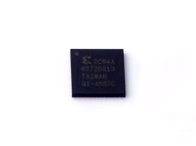
The 10M08SCU169I7G FPGA from Intel is widely recognized for its Power ful performance and reliability in complex applications. However, like all sophisticated systems, it can encounter occasional issues. This article explores common troubleshooting strategies and effective solutions to ensure your FPGA operates seamlessly.
10M08SCU169I7G, FPGA troubleshooting, Intel FPGA, 10M08SCU169I7G solutions, FPGA errors, FPGA performance, common FPGA issues, FPGA debugging, Intel FPGA solutions.
Understanding the 10M08SCU169I7G and Identifying Common Issues
The 10M08SCU169I7G is part of Intel’s MAX 10 series of FPGAs, known for its small form factor, low power consumption, and impressive flexibility. The 10M08SCU169I7G, specifically, offers 8,640 logic elements and up to 476 I/O pins, making it ideal for a variety of embedded applications such as industrial control, automotive, consumer electronics, and telecommunications. Despite its versatility, like any complex system, it can face technical difficulties during development or deployment. Understanding how to identify and troubleshoot common issues with the 10M08SCU169I7G is crucial for ensuring smooth operation.
1.1 Power and Connectivity Issues
One of the most frequent issues encountered with FPGAs, including the 10M08SCU169I7G, is power-related problems. If the FPGA does not receive the correct voltage levels, it may fail to boot, malfunction, or even become permanently damaged. The 10M08SCU169I7G requires 3.3V and 1.2V for its core and I/O functionality, respectively. Common symptoms of power issues include failure to start, unexpected resets, or unpredictable behavior during operation.
Solution:
Verify power supply levels: Use a multimeter to confirm that the FPGA is receiving the correct voltage levels at the designated power pins.
Check for power noise: Excessive noise in the power supply could cause intermittent failures. Ensure that the power source is stable and filtered.
Inspect for short circuits: Make sure that no pins are shorted to ground or to each other, as this can cause power surges that might damage the FPGA.
1.2 Configuration Failures
FPGA configuration issues are common and can manifest in various ways. If your FPGA fails to load the design, it may indicate an issue with the configuration process, the bitstream file, or the programming tool.
Solution:
Check the configuration files: Ensure that the bitstream file is correctly generated and compatible with the FPGA model. Use Intel's Quartus software to verify the integrity of the bitstream file.
Reprogram the FPGA: Try reprogramming the FPGA using different programming modes or interface s (e.g., JTAG or USB-Blaster).
Inspect programming connections: Loose or faulty connections between the programming hardware and the FPGA can result in configuration failures. Ensure all connectors are secure and correctly oriented.
1.3 Signal Integrity and Timing Issues
Signal integrity problems and timing violations are often at the root of operational failures in FPGAs, especially when dealing with high-speed circuits. Issues such as signal reflections, crosstalk, and improper timing constraints can cause unexpected behavior, including incorrect outputs, data loss, or malfunctioning peripherals.
Solution:
Check signal routing: Ensure that traces are kept as short as possible, especially for high-frequency signals. Use proper trace widths and spacing to minimize noise and signal degradation.
Use proper termination: Implement proper termination techniques to reduce reflections and maintain signal integrity.
Review timing constraints: Using Intel’s Quartus software, ensure that all timing constraints are met. You can also perform static timing analysis to identify and resolve any violations.
Advanced Troubleshooting Techniques and Preventative Solutions for the 10M08SCU169I7G
While basic troubleshooting steps can resolve many issues, more advanced techniques may be required for persistent problems or complex setups. Additionally, preventative solutions can help avoid common pitfalls and enhance the longevity and reliability of the 10M08SCU169I7G.
2.1 Debugging Using On-Chip Resources
Intel FPGAs, including the 10M08SCU169I7G, are equipped with on-chip debugging resources that can be invaluable when tracking down elusive problems. Features like SignalTap Logic Analyzer and Integrated Logic Analyzer (ILA) allow engineers to capture real-time signal data from the FPGA and analyze it to diagnose issues. Using these tools can help identify signal glitches, timing issues, or logic errors that may be affecting the FPGA’s performance.
Solution:
Enable SignalTap Logic Analyzer: Use SignalTap to capture internal signal states and analyze them in real-time. This can help pinpoint problematic signals or timing mismatches.
Use Integrated Logic Analyzer (ILA): If you're dealing with high-speed data or complex logic sequences, the ILA can be configured to monitor specific signals during operation and generate a comprehensive report of their behavior.
2.2 Overheating and Thermal Management
Another issue that can cause intermittent or permanent failures in the 10M08SCU169I7G is overheating. If the FPGA exceeds its recommended operating temperature (typically 0°C to 100°C), it can result in system instability or permanent damage to internal components. Overheating may be caused by inadequate heat dissipation or excessive power consumption.
Solution:
Monitor the temperature: Ensure that the FPGA is operating within the manufacturer’s recommended temperature range. Use thermal sensors and infrared thermometers to check the temperature during operation.
Improve cooling solutions: If the FPGA is overheating, enhance the thermal management by adding heat sinks, improving airflow in the enclosure, or using active cooling methods such as fans.
Consider power optimization: Reduce unnecessary power consumption by disabling unused features or by optimizing the FPGA configuration to reduce heat output.
2.3 Pin and I/O Configuration Issues
Misconfigurations in the FPGA’s I/O pins are a common source of issues. Incorrect I/O pin assignments, improper voltage levels, or insufficient current-driving capabilities can lead to unreliable operation. For example, if I/O pins are assigned to the wrong voltage standards (e.g., 3.3V I/O signals on 1.8V pins), the FPGA may not communicate correctly with other devices or external peripherals.
Solution:
Review pin assignments: Double-check the pin assignments in the Quartus project to ensure they match the physical connections on your PCB. Utilize the Quartus Pin Planner tool to visually validate assignments.
Check I/O voltage levels: Ensure that the I/O pins are configured with the correct voltage standards. Use the I/O Standard settings in Quartus to confirm the proper configuration for your target system.
Test with external peripherals: If the FPGA communicates with external components, check the signal integrity and verify that the I/O configuration is compatible with the requirements of the connected devices.
2.4 Firmware and Software Updates
In some cases, issues with the 10M08SCU169I7G can be related to outdated firmware or software tools. As Intel continuously releases updates to its development tools and device firmware, staying up-to-date is critical for fixing bugs, improving stability, and ensuring compatibility with the latest technology.
Solution:
Update Quartus Software: Regularly check for new versions of Intel Quartus and apply any relevant patches or updates to ensure you have the latest bug fixes and feature enhancements.
Update device firmware: Verify that the FPGA’s internal firmware is up-to-date. Intel’s website or Quartus software can help you identify the latest firmware versions and guide you through the update process.
2.5 Preventative Measures for Long-Term Reliability
Once you have resolved immediate issues with the 10M08SCU169I7G, it’s important to take steps to prevent future failures and enhance system reliability over the long term. Following best practices during design, assembly, and testing can save time and effort down the road.
Solution:
Adhere to best design practices: Use appropriate PCB layout techniques, such as proper grounding, minimal via usage, and optimized routing for high-speed signals. These practices will minimize the risk of signal integrity issues.
Perform regular testing: Before final deployment, thoroughly test the FPGA under varying conditions to uncover any hidden issues. Use tools like the built-in logic analyzer to monitor performance during stress tests.
Document your configurations: Keep a detailed record of your FPGA configuration, pin assignments, voltage settings, and any custom logic. This documentation will be invaluable if issues arise in the future and will streamline troubleshooting processes.
In conclusion, troubleshooting the 10M08SCU169I7G FPGA involves a systematic approach to diagnosing power, configuration, timing, and signal integrity issues. By leveraging both basic and advanced troubleshooting techniques, and by implementing preventative measures, engineers can ensure reliable operation and extend the life of their FPGA-based systems. Regular updates to software tools and firmware, along with a focus on long-term reliability, will help avoid many common issues and keep your projects running smoothly.
If you are looking for more information on commonly used Electronic Components Models or about Electronic Components Product Catalog datasheets, compile all purchasing and CAD information into one place.
Partnering with an electronic components supplier sets your team up for success, ensuring the design, production, and procurement processes are quality and error-free.


