Common Troubleshooting Issues with the XC2C64A-7QFG48C and How to Resolve Them
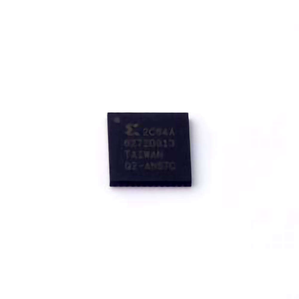
The XC2C64A-7QFG48C, a member of Xilinx's CoolRunner-II family of CPLDs , is widely used in digital design for applications such as embedded systems, Communication s, automotive, and consumer electronics. Like any complex programmable logic device, the XC2C64A can encounter a variety of issues that may hinder performance or cause failure in your circuits. Understanding these problems and implementing proper troubleshooting strategies is essential for any engineer working with this device.
1. Power Supply Issues
Problem: Inadequate Power to the Device
A common issue in many CPLD designs is power supply failure or instability. The XC2C64A-7QFG48C requires a stable 3.3V power supply, and fluctuations can result in improper behavior or complete failure to function.
Solution:
To resolve power issues, start by checking the power rail with an oscilloscope or a digital multimeter. Ensure that the 3.3V supply is stable and within the specified tolerance (typically ±5%). If you detect any noise or instability, check the decoupling capacitor s on the VCC and GND pins of the device. Adding more capacitors or using higher-quality ones could help smooth out any fluctuations.
If the power supply is correctly rated but still inconsistent, ensure that the power supply is properly grounded and that no ground loops or voltage drops are affecting the signal integrity.
2. Configuration Problems
Problem: Failure to Configure the Device
The XC2C64A-7QFG48C is configured via a JTAG interface or through an external configuration device, depending on the design requirements. If the configuration file is corrupted, the device may fail to initialize correctly, leaving your system inoperable.
Solution:
Start by checking the integrity of the configuration file. This can often be done by reloading the configuration or using a programmer/debugger to ensure that the configuration process completes successfully. If the file is corrupted, it may be necessary to regenerate the bitstream file from the original design source.
Next, verify the connections to the JTAG interface or configuration device. Ensure that the TDI, TDO, TMS, and TCK pins are correctly wired and there are no open or short circuits. Poor connections in the configuration path can result in incomplete configuration or failure to configure at all.
If the device has been configured previously but is no longer working, perform a reset and re-load the configuration. You can also check for problems with the power-on reset circuitry that might prevent the device from entering the correct state after power is applied.
3. Signal Integrity Issues
Problem: Unstable or Distorted Signals
Signal integrity is crucial for the proper functioning of the XC2C64A-7QFG48C, especially when working with high-speed signals. Issues like reflections, cross-talk, and noise can lead to unreliable performance or failure of specific logic functions.
Solution:
To troubleshoot signal integrity issues, first ensure that your PCB layout follows the recommended guidelines. For example, pay attention to trace impedance, minimize trace lengths, and avoid sharp angles in signal traces. If the system is clocked at high speeds, it is essential to use proper termination and differential signaling where applicable.
Use an oscilloscope to check for signal quality at key locations. Look for signs of reflections, ringing, or other anomalies that can be caused by improper PCB routing or grounding. If you notice any signal degradation, try adjusting the trace lengths or adding additional decoupling capacitors to the power supply to improve noise immunity.
Another key consideration is the clock signal. Ensure that the clock inputs are clean and stable. A noisy clock signal can cause the entire system to malfunction, so use an external clock buffer if necessary to strengthen the clock signal integrity.
4. I/O Pin Configuration Problems
Problem: Incorrect I/O Pin Behavior
The XC2C64A-7QFG48C has configurable I/O pins that can be used as inputs, outputs, or bidirectional signals. If your design requires a specific I/O behavior, any misconfiguration or conflict in I/O pin settings can cause erratic operation, leading to logic errors or communication failures.
Solution:
Check the I/O pin settings in the configuration software. Ensure that the I/O pins are correctly assigned as inputs, outputs, or bidirectional, as needed. If there are any conflicts (e.g., two pins trying to drive the same signal), this can cause significant issues in your circuit.
You should also verify that all I/O pins have the appropriate drive strength set and that there are no conflicts with internal pull-up or pull-down resistors that could interfere with external components. In high-speed designs, it is critical to check the Timing requirements for each I/O pin to ensure they meet the specifications for your application.
5. Device Overheating
Problem: Device Temperature Too High
The XC2C64A-7QFG48C is designed to operate within a specific temperature range. However, high power consumption, insufficient heat dissipation, or poor environmental conditions can cause the device to overheat, leading to failure or reduced performance.
Solution:
Monitor the temperature of the device using a temperature probe or thermal camera. If overheating is detected, try to reduce the power consumption of the device by optimizing the design to reduce logic switching or simplifying the functions. Adding additional heat sinks or improving ventilation around the device can also help dissipate heat more effectively.
If the device continues to overheat despite these measures, consider switching to a lower-power variant of the XC2C64A-7QFG48C or reevaluating the overall system design to improve heat management.
Advanced Troubleshooting Techniques and Additional Solutions for the XC2C64A-7QFG48C
While the previous section covers some of the most common issues engineers face when working with the XC2C64A-7QFG48C, advanced troubleshooting techniques are necessary for more complex problems. Below, we explore additional solutions and best practices to ensure the device functions optimally.
6. Firmware Bugs and Design Errors
Problem: Logic Design Errors or Firmware Bugs
Sometimes, the issue isn't with the physical device or external components but with the firmware or logic implemented on the device. Errors in VHDL or Verilog code can lead to unintended behavior, even though the hardware seems to be functioning correctly.
Solution:
Carefully review the source code for logical errors, race conditions, or other bugs that could be causing incorrect outputs. Simulating the design using tools such as Xilinx’s ISE or Vivado can help identify potential issues before they manifest in hardware.
If the design is complex, consider breaking it down into smaller module s and testing them individually to isolate the source of the problem. Using testbenches during simulation can help identify logical flaws in the design before physical implementation.
Additionally, using a logic analyzer or embedded debugging tools can provide insight into the internal signals of the XC2C64A during operation. This allows you to monitor the real-time behavior of the device and pinpoint where the logic might be failing.
7. Timing Violations and Constraints
Problem: Timing Violations
Timing violations can occur when the internal logic of the XC2C64A cannot complete a signal transition within the specified timing constraints. This can lead to incorrect operation, especially in high-speed designs.
Solution:
Review the timing constraints of your design to ensure that all signal paths meet the required setup and hold times. Utilize the timing analysis tools provided by Xilinx, such as the Timing Analyzer in Vivado, to check if any paths are failing to meet timing requirements.
If violations are found, try to optimize the critical paths by shortening the signal routes, increasing the clock frequency, or improving the logic implementation. In some cases, adding pipeline stages or increasing the clock speed may alleviate the problem.
8. Unresponsive JTAG Interface
Problem: JTAG Interface Not Responding
If you're using JTAG for debugging or programming the XC2C64A-7QFG48C, issues with the JTAG interface can prevent successful communication. This could be due to incorrect connections, faulty cables, or issues with the JTAG programmer.
Solution:
First, check the physical connections between the JTAG programmer and the device. Verify that all pins are correctly connected and that there are no open or shorted connections. If the connections are fine, try using a different JTAG programmer or cable to rule out hardware issues.
Additionally, ensure that the JTAG interface is enabled in the device configuration settings. Some designs may have the JTAG interface disabled by default, and this can be corrected by adjusting the programming settings.
9. Data Corruption in Communication Systems
Problem: Data Corruption During Communication
In systems where the XC2C64A is used for communication, data corruption can occur due to signal integrity problems, improper voltage levels, or incorrect protocol implementation.
Solution:
Carefully check the communication protocol to ensure that all timing parameters are correctly defined and that there are no mismatches in data width, clock polarity, or other important parameters. If you're using differential signaling (e.g., LVDS), check the differential pair routing on the PCB and ensure that the impedance is properly matched.
Using error-checking methods, such as CRC (Cyclic Redundancy Check), can help detect and correct any data corruption that might occur during communication.
10. Final Checks and System Validation
Once you've addressed all the common and advanced troubleshooting techniques, it's important to perform a final validation of the system. Run your design through extensive testing to ensure all features are functioning as expected under a range of conditions. This can include:
Running stress tests to verify system stability
Checking for overcurrent conditions
Verifying correct behavior under extreme environmental conditions (temperature, voltage, etc.)
Reviewing the system as a whole to ensure the XC2C64A-7QFG48C interacts correctly with other components
By following these troubleshooting and solution strategies, engineers can overcome many of the common challenges they face when working with the XC2C64A-7QFG48C. This detailed approach helps ensure that your device runs efficiently and reliably, ultimately leading to successful project completion.
If you are looking for more information on commonly used Electronic Components Models or about Electronic Components Product Catalog datasheets, compile all purchasing and CAD information into one place.
Partnering with an electronic components supplier sets your team up for success, ensuring the design, production, and procurement processes are quality and error-free.


