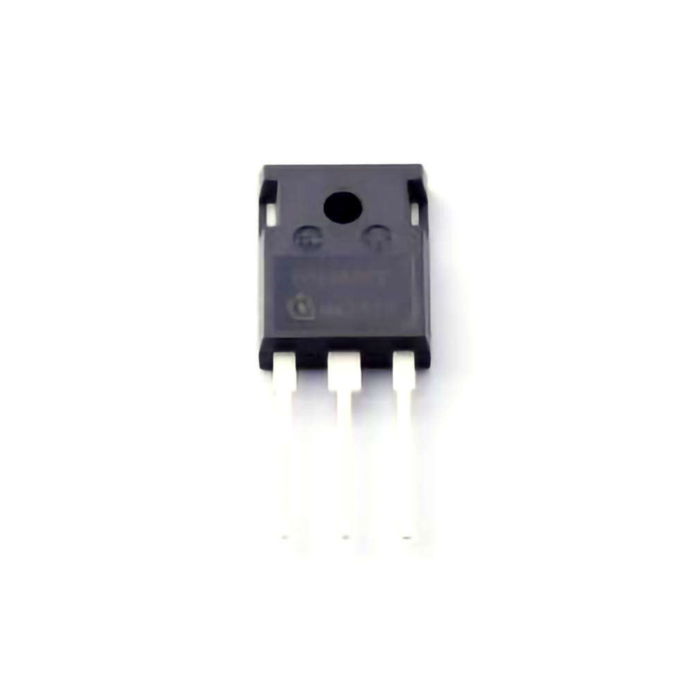
The IPW60R060P7 is a popular high-performance IGBT module used in various applications, including motor control, power electronics, and renewable energy systems. However, like any complex electronic component, it may encounter issues during operation. This article explores common troubleshooting scenarios and provides practical solutions to enhance the reliability and longevity of the IPW60R060P7.
Understanding the IPW60R060P7 and Common Troubleshooting Scenarios
The IPW60R060P7 is a widely used Insulated Gate Bipolar Transistor (IGBT) module, renowned for its efficiency and reliability in high-power applications. It finds use in a range of systems, including motor drives, renewable energy converters, and high-efficiency inverters. Despite its robust design, the module is not immune to faults or performance degradation, which can lead to system failures. To maintain optimal performance and extend the service life of your system, understanding the common issues and knowing how to troubleshoot them is crucial.
1.1. Overheating and Thermal Stress
Overheating is one of the most common issues in power electronics, and it significantly affects the IPW60R060P7’s functionality. This IGBT module, like any semiconductor device, has a maximum junction temperature specification, typically around 150°C. When exposed to excessive heat, the internal components of the IGBT can degrade, leading to failure.
Common Causes:
Inadequate cooling: Insufficient heat sinking or improper cooling systems can cause excessive temperatures.
Overcurrent operation: If the module is asked to handle currents beyond its rated capacity, it will generate excess heat.
Improper ventilation: Poor airflow around the module or installation in a confined space can exacerbate heat buildup.
Solutions:
Improve cooling efficiency: Ensure that the heat sink is properly mounted and that thermal paste or conductive pads are applied correctly.
Upgrade the cooling system: Use high-quality active cooling systems like fans or liquid cooling where applicable.
Check air circulation: Ensure the surrounding environment has adequate ventilation, and avoid placing the module in tight, enclosed spaces.
By addressing thermal issues, you can prevent premature module failure and maintain system reliability.
1.2. Short Circuit or Overvoltage Protection Activation
The IPW60R060P7, like all IGBT modules, features built-in protection against overvoltage and short circuits. These protection mechanisms are designed to shield the module from catastrophic failure, but they can also trigger under certain operating conditions, which could disrupt system performance.
Common Causes:
Load faults: If the connected load experiences a short circuit or a high-voltage spike, the protection circuitry will automatically activate.
Inadequate snubber circuit: A snubber circuit is used to suppress voltage spikes that could otherwise damage the IGBT. An improperly designed or malfunctioning snubber can cause unnecessary triggering of protection.
Faulty gate drive: Issues with the gate driver, such as improper voltage levels or malfunctioning components, can also lead to unintended triggering.
Solutions:
Inspect the load: Make sure the load does not exceed the current and voltage ratings specified for the IPW60R060P7.
Check snubber components: Regularly inspect and replace snubber circuit components to prevent voltage spikes from damaging the IGBT.
Examine gate drive circuit: Test the gate drive for any irregularities. Ensure that the gate voltage is within the specified range, and the driver is operating correctly.
By identifying and addressing these protection mechanisms, you can prevent unnecessary shutdowns and extend the life of your IGBT module.
1.3. Gate Drive Issues
The gate drive circuitry plays a critical role in the switching performance of IGBT modules. If the gate drive is faulty or improperly configured, it can lead to improper switching of the IPW60R060P7, resulting in reduced performance or even permanent damage to the module.
Common Causes:
Insufficient gate drive voltage: The IPW60R060P7 requires a specific voltage to turn on and off effectively. If the gate voltage is too low, the module may not switch completely, resulting in heating and inefficiency.
Gate drive timing issues: Incorrect timing between the gate signal and the current flow can lead to partial or delayed switching, causing the module to overheat.
Damaged gate driver components: Transistors, resistors, or capacitor s in the gate driver circuit may degrade over time and fail, leading to malfunctioning gate signals.
Solutions:
Check gate voltage: Use an oscilloscope to monitor the gate voltage and ensure that it meets the required specifications.
Examine gate drive timing: Ensure that the gate drive signal has the correct timing relative to the power stage.
Replace damaged components: If there are signs of wear or failure in the gate driver, replace the faulty components to restore proper functionality.
Proper gate drive is essential for the efficient switching of IGBTs, so always ensure your gate driver circuit is functioning within the recommended parameters.
1.4. Insulation and Dielectric Failure
The IPW60R060P7 is designed with insulation between the control circuit and the power circuit, preventing electrical interference and ensuring safety. However, insulation breakdown due to age, thermal stress, or high-voltage spikes can cause short circuits or electrical leakage.
Common Causes:
High-voltage transients: Voltage spikes caused by switching transients or lightning can exceed the insulation’s rating.
Thermal cycling: Repeated heating and cooling of the module can degrade the insulation materials over time.
Environmental contamination: Dust, moisture, or corrosive chemicals can deteriorate insulation and cause failure.
Solutions:
Use surge protection: Install surge protection devices to shield the module from excessive voltage spikes.
Avoid excessive temperature fluctuations: Ensure that the IPW60R060P7 operates within its rated thermal limits.
Regular cleaning and inspection: Regularly clean the module and its surroundings to avoid contamination that could compromise the insulation.
By maintaining proper insulation, you can avoid short circuits and ensure the safe operation of the IPW60R060P7.
Advanced Troubleshooting and Maintenance Solutions
While the common troubleshooting techniques discussed in Part 1 can solve many issues, advanced troubleshooting and regular maintenance are crucial for ensuring the long-term reliability of the IPW60R060P7 IGBT module. Here, we’ll delve into more advanced troubleshooting steps and maintenance practices that can prevent problems from arising in the first place.
2.1. Voltage and Current Measurement
When troubleshooting the IPW60R060P7, precise voltage and current measurement is essential. If the module experiences performance issues, measuring the voltage at key points can reveal insights into whether the module is receiving the correct gate signal or experiencing excessive voltage.
Steps for Measurement:
Measure gate-to-emitter voltage (VGE): Check the VGE voltage during operation to ensure it’s within the recommended operating range (usually 15V to 20V).
Monitor collector-emitter voltage (VCE): Measure the VCE during operation to check for excessive voltage spikes that could indicate a fault.
Monitor current: Use a current probe to measure the current flowing through the module. Ensure the current is within the rated specifications for the IPW60R060P7.
Solution:
Regular monitoring of voltage and current can help identify early signs of distress and allow corrective action before more severe damage occurs.
2.2. Stress Testing and Burn-In
Stress testing is a valuable technique for identifying potential weaknesses in IGBT modules. Burn-in tests subject the module to operating conditions beyond normal levels to accelerate aging and identify latent defects.
Procedure:
Run a thermal cycle test: Subject the module to thermal cycles, from cold to hot conditions, to simulate real-world thermal stress.
Overload testing: Gradually increase the load on the module while monitoring its performance, checking for abnormal temperature rise or failure to switch.
Vibration tests: For modules used in environments with significant vibration, subject the module to vibration testing to ensure its mechanical integrity.
Solution:
By performing regular stress testing and burn-in procedures, you can identify weak components that might fail under stress and replace them before a catastrophic failure occurs.
2.3. Visual Inspection for Physical Damage
One of the simplest but most effective troubleshooting techniques is a visual inspection. Over time, the IPW60R060P7 may exhibit signs of physical wear, such as discoloration, cracks, or soot marks, which can provide critical clues about underlying issues.
What to Look For:
Discoloration: Yellow or brownish discoloration around the terminals or package indicates overheating or thermal stress.
Cracks or chips: Mechanical stress or thermal cycling can cause cracks or chips in the module's packaging, which may lead to electrical shorts or insulation failure.
Burn marks: These are a clear sign of excessive current or voltage spikes that have caused arcing.
Solution:
If any visible damage is found, replace the module or any affected components immediately to prevent further damage to the system.
2.4. Regular Firmware and Software Updates
In systems where the IPW60R060P7 is used as part of a larger controller or inverter, software and firmware updates can be critical for ensuring that the module operates optimally. Firmware bugs, improper configurations, or outdated software can lead to improper switching behavior and inefficiencies.
Solution:
Always ensure that the firmware and software controlling the IGBT module are up-to-date. Manufacturers frequently release updates to improve performance, add new features, and resolve known issues.
2.5. Preventative Maintenance
Preventative maintenance is one of the most effective ways to extend the life of your IPW60R060P7 IGBT module and avoid unexpected failures. Scheduled inspections and maintenance routines can identify issues before they become critical.
Key Maintenance Tasks:
Periodic cleaning: Keep the module free of dust and contaminants that can cause overheating or insulation breakdown.
Reapply thermal paste: If the module is subject to frequent thermal cycles, replace the thermal paste to ensure efficient heat transfer.
Inspect for loose connections: Periodically check for loose or damaged electrical connections, which can lead to arcing and module failure.
Solution:
By integrating regular preventative maintenance into your operational routine, you can significantly reduce the likelihood of encountering severe issues with the IPW60R060P7.
Conclusion
The IPW60R060P7 is a highly reliable IGBT module, but it is not immune to the challenges associated with high-power applications. By understanding common troubleshooting scenarios, performing advanced diagnostic procedures, and implementing a proactive maintenance plan, you can ensure the long-term reliability and optimal performance of this essential component in your power electronics systems. Remember, early detection and timely intervention are the ultimate keys to preventing costly repairs and extending the lifespan of your IGBT modules.
If you are looking for more information on commonly used Electronic Components Models or about Electronic Components Product Catalog datasheets, compile all purchasing and CAD information into one place.
Partnering with an electronic components supplier sets your team up for success, ensuring the design, production, and procurement processes are quality and error-free.


