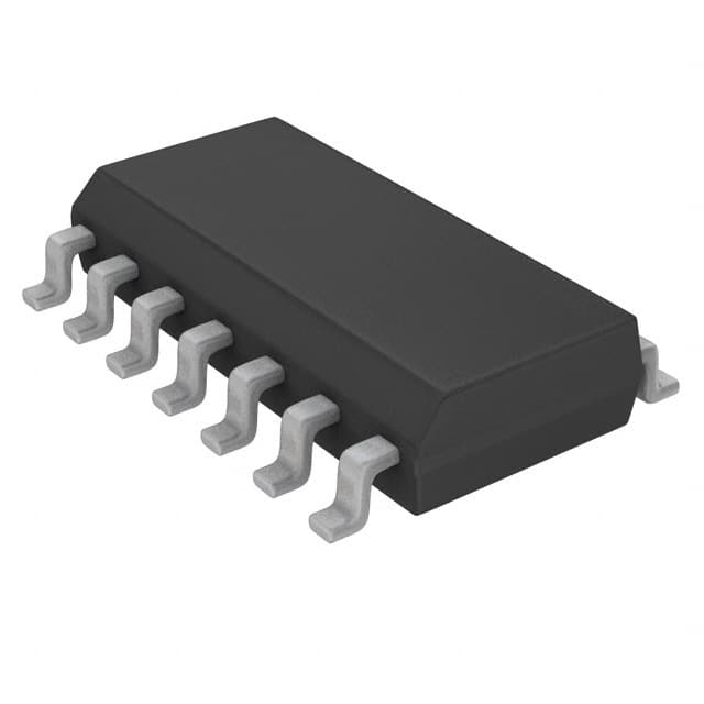
Understanding the PIC16F616-I/SL and Common Issues
The PIC16F616-I/SL is a widely-used microcontroller from Microchip Technology, offering a 14-bit instruction set and a wide range of built-in peripherals, making it a popular choice for many embedded applications. However, like any piece of hardware, users can sometimes face issues that may cause their project to fail or malfunction. Troubleshooting these problems can often be tricky without a solid understanding of the system's architecture and behavior.
In this article, we’ll examine some of the common issues that arise with the PIC16F616-I/SL, explore possible causes, and provide detailed solutions to resolve these problems efficiently.
Overview of the PIC16F616-I/SL
The PIC16F616-I/SL is a low- Power , high-performance microcontroller featuring a 16-bit program counter, an 8-bit data bus, and an integrated EEPROM Memory . It is widely employed in applications requiring a high level of reliability and flexibility, such as sensor monitoring, motor control, and other embedded tasks.
It includes:
8-bit CPU: A core that processes commands in 8-bit chunks.
32 bytes of RAM: For temporary storage and data manipulation.
Memory Options: Flash program memory and EEPROM for data retention.
Analog features: Includes ADC (Analog-to-Digital Conversion) capabilities and Comparators for mixed-signal applications.
I/O Pins: Supports up to 14 GPIO pins, allowing flexibility in interfacing with other components.
Given its versatility, the PIC16F616-I/SL is commonly used in everything from simple automation systems to sophisticated robotics and Communication devices.
Common Troubleshooting Areas
Understanding common issues that can occur during development is crucial for addressing them promptly. Let’s explore the major areas where developers encounter problems when working with the PIC16F616-I/SL:
1. Power Supply Issues
The first and most fundamental issue that can arise is inadequate or unstable power supply. Power problems can prevent the microcontroller from functioning correctly, leading to erratic behavior or failure to boot up altogether.
Symptoms:
The PIC16F616 fails to power on.
The microcontroller resets continuously.
The device operates intermittently or unexpectedly shuts down.
Causes:
Inconsistent or noisy power supply.
Incorrect voltage levels.
Lack of proper decoupling capacitor s.
Solution:
Verify that the voltage supplied to the microcontroller matches the required operating voltage (typically 5V or 3.3V depending on your configuration).
Use high-quality capacitors close to the power pins of the microcontroller to filter out noise and stabilize the supply.
Check for possible voltage spikes or drops using an oscilloscope to ensure stable power delivery.
2. Reset Pin Problems
The reset pin (MCLR) is critical for initiating the microcontroller. If the reset circuit is not properly designed, the microcontroller might not start up correctly or could enter an undesired state.
Symptoms:
Microcontroller does not start after powering on.
It behaves unpredictably after reset.
The microcontroller seems "stuck" in a particular program state.
Causes:
The reset pin is floating or not correctly pulled high or low.
Incorrect external reset circuitry.
No proper reset delay or debounce circuit.
Solution:
Ensure that the MCLR pin is properly connected to the power and reset components as per the datasheet's recommendations.
Add a pull-up resistor to the MCLR pin if necessary, and ensure it is connected to a stable voltage source.
Check the reset circuitry to ensure that it delivers a clean reset pulse to the PIC16F616.
3. I/O Pin Misconfigurations
Incorrect configuration of the microcontroller’s I/O pins is a common issue, especially in embedded systems with a variety of peripheral devices.
Symptoms:
I/O pins not responding to inputs or outputs.
Communication failures with external devices.
Unexpected voltage levels or incorrect logic states on the pins.
Causes:
Incorrect pin direction setting (input/output mismatch).
Pins configured for analog input when digital signals are expected.
Lack of proper pull-up or pull-down resistors on certain pins.
Solution:
Double-check your pin configurations in your software, especially the TRIS register, which controls the direction of the pins (input or output).
Ensure that digital pins are not set as analog if they are supposed to communicate with digital devices.
Use pull-up or pull-down resistors as necessary, especially for input pins that need a defined logic level.
4. Clock Source Problems
Clock-related issues can often cause the microcontroller to fail or behave unpredictably. The PIC16F616-I/SL supports several clock sources, including internal and external oscillators.
Symptoms:
Microcontroller does not respond to commands.
The device runs at an incorrect speed.
Peripheral devices fail to communicate.
Causes:
Incorrect configuration of the clock source.
Mismatched clock frequencies between the microcontroller and external peripherals.
Noise or interference affecting the clock signal.
Solution:
Verify that the clock source is configured correctly in the FUSES register. The PIC16F616 supports several oscillator types, such as the internal 8MHz RC oscillator, external crystal, or an external oscillator module .
Ensure that the clock frequency aligns with the requirements of your application and peripherals.
Use an oscilloscope to monitor the clock signal and ensure it is stable and free from noise.
5. ADC (Analog-to-Digital Conversion) Issues
If your project involves analog sensors, the ADC functionality of the PIC16F616 is likely being used. However, ADC issues are common when the signal conditioning or software configuration is incorrect.
Symptoms:
Incorrect ADC readings.
ADC conversions take too long or don’t complete.
No data is returned from the ADC module.
Causes:
Incorrect ADC configuration (e.g., reference voltage or resolution setting).
Floating analog input pins.
Insufficient sampling time.
Solution:
Check the configuration of the ADC module, ensuring the correct reference voltage and resolution settings are used.
Ensure analog input pins are properly conditioned, meaning they are not floating and have a defined voltage level.
Adjust the ADC sampling time if necessary to ensure accurate conversions.
Advanced Troubleshooting Techniques for the PIC16F616-I/SL
Troubleshooting embedded systems, especially microcontroller-based systems like the PIC16F616, requires patience and an understanding of more advanced diagnostic techniques. The issues we discussed in Part 1 are only the beginning. Below, we will delve into more complex problems and provide solutions that involve deeper debugging techniques.
6. Communication Failures
The PIC16F616 supports several communication protocols, including SPI, I2C, and UART, which are commonly used for interfacing with external components. Communication failures can be difficult to diagnose, as they may involve several layers of hardware and software.
Symptoms:
Data transfer is corrupted or incomplete.
Devices fail to respond during communication.
The microcontroller fails to send or receive signals.
Causes:
Incorrect baud rate or clock settings.
Poor signal integrity or wiring issues.
Incorrect software configuration (e.g., wrong SPI mode or I2C addressing).
Solution:
Double-check the communication settings, including the baud rate for UART or the clock rate for SPI and I2C.
Use a logic analyzer or oscilloscope to monitor the communication signals and ensure they conform to the expected timing and voltage levels.
Verify that external devices are properly connected and that there are no short circuits or open lines in the communication bus.
7. Interrupt-Related Issues
Interrupts are essential for handling time-sensitive tasks in embedded systems. However, interrupt mismanagement or failure to configure interrupts correctly can lead to significant issues.
Symptoms:
Interrupts don’t trigger.
The program execution hangs at interrupt service routines (ISRs).
Interrupt priorities conflict, causing missed interrupts.
Causes:
The interrupt priority is incorrectly configured.
Global or peripheral interrupt enable bits are not set.
Interrupt flags are not cleared after the ISR.
Solution:
Review the interrupt configuration, including enabling global interrupts and peripheral interrupts.
Ensure that interrupt flags are properly cleared at the end of the ISR.
If multiple interrupts are enabled, ensure that priority levels are correctly set to avoid conflicts.
8. Overheating and Thermal Issues
While not a software issue, thermal management is an essential part of ensuring the stability of the PIC16F616 and the system it is embedded in. Overheating can lead to hardware failures or erratic behavior.
Symptoms:
Microcontroller becomes excessively hot.
System resets or malfunctions after running for a while.
The performance degrades over time.
Causes:
Insufficient heat dissipation.
Power supply inefficiencies leading to excessive heat.
Heavy processing loads causing high current draw.
Solution:
Implement passive cooling solutions, such as heat sinks, to dissipate heat.
Check the power supply and ensure it is providing a stable voltage at the required current levels.
Monitor the temperature of the microcontroller during operation, especially in demanding applications, to ensure it remains within safe limits.
9. Software Debugging and Debugging Tools
In addition to hardware checks, thorough software debugging is often necessary to identify the root cause of issues. Using proper debugging tools is essential for identifying subtle bugs that are difficult to detect with just hardware testing.
Symptoms:
The microcontroller works intermittently, or not at all, depending on the software.
Incorrect program behavior.
Unexpected resets or program flow.
Causes:
Incorrect logic in the software.
Uninitialized variables or register settings.
Stack overflow or memory corruption.
Solution:
Use MPLAB X IDE with an in-circuit debugger (ICD) or a simulator to step through the code and monitor variables.
Implement logging or debugging output (via UART or other serial communication protocols) to track the software flow.
Check memory usage carefully to prevent stack overflow or memory corruption that may affect the program's behavior.
In conclusion, troubleshooting the PIC16F616-I/SL involves both hardware and software diagnostics. By following the solutions provided here and using the right tools, developers can efficiently identify and resolve issues, ensuring their embedded systems run smoothly and reliably.
If you are looking for more information on commonly used Electronic Components Models or about Electronic Components Product Catalog datasheets, compile all purchasing and CAD information into one place.
Partnering with an electronic components supplier sets your team up for success, ensuring the design, production, and procurement processes are quality and error-free.


