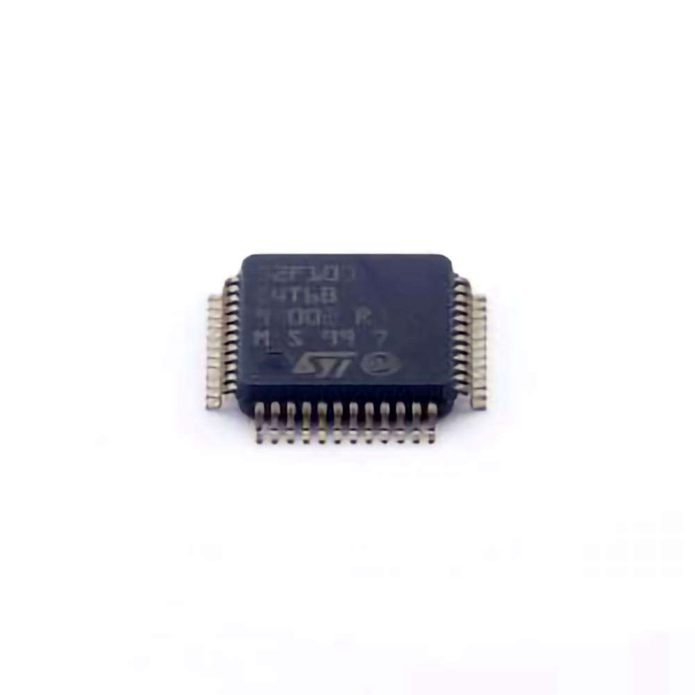
Identifying and Addressing Hardware Issues in STM32F100C4T6B
The STM32F100C4T6B, part of the STM32F1 series from STMicroelectronics, is a versatile and cost-effective microcontroller designed for a variety of embedded applications. Despite its robust architecture, developers may encounter challenges when working with this MCU. Hardware-related issues are common in embedded systems, and understanding how to diagnose and resolve them is crucial for the success of your project.
1. Power Supply Issues
One of the first areas to check when troubleshooting any microcontroller is the power supply. If the STM32F100C4T6B isn't behaving as expected, or if it isn't booting up at all, power-related problems could be at the root of the issue.
Symptoms of Power Supply Issues:
The microcontroller does not start or reset correctly.
Unstable operation or unexpected resets during runtime.
Peripheral module s connected to the MCU fail to operate.
Solutions:
Check Voltage Levels: Ensure that the supply voltage to the STM32F100C4T6B is within the specified range (2.0V to 3.6V). Measure the voltage with a multimeter or oscilloscope to ensure consistency. Any fluctuation outside this range may cause the MCU to malfunction or even be damaged.
Decoupling Capacitors : Use proper decoupling capacitor s (typically 100nF or 10µF) near the power pins of the MCU. This helps filter out noise and smooth the supply voltage, which is crucial for stable operation.
Check Power Connections: Verify that all power pins (VDD, VSS, etc.) are securely connected and there are no short circuits.
2. Clock Source Problems
The STM32F100C4T6B requires an external clock source for accurate timekeeping and system operation. Common clock-related issues include failure to start up, running at the wrong frequency, or erratic behavior due to improper clock configuration.
Symptoms of Clock Issues:
The MCU appears to freeze or behaves erratically.
Timers and peripherals that rely on the clock (such as UART or I2C) fail to operate correctly.
The microcontroller does not run at the expected frequency.
Solutions:
Check External Crystal or Oscillator: If you are using an external crystal or oscillator, verify that the component is correctly mounted and connected. The STM32F100C4T6B typically requires a 8 MHz external crystal for proper operation. Use an oscilloscope to verify the clock signal's presence and frequency.
Internal Clock Configuration: If you are using the internal RC oscillator, ensure that the system clock configuration in the firmware is set to use the correct source. Incorrect configuration could result in the MCU running at an unintended frequency.
Clock Pin Connections: Inspect the clock input pins (HSE, LSE) and ensure they are not floating or shorted. If using an external crystal, confirm that the load capacitors are correctly chosen based on the crystal's specifications.
3. Reset Circuit Issues
The STM32F100C4T6B includes an internal reset functionality, but external reset circuits are commonly used to ensure proper startup. Issues with the reset circuit can cause the microcontroller to either fail to reset properly or continuously reset, disrupting operation.
Symptoms of Reset Circuit Problems:
The MCU constantly resets and never completes its startup sequence.
Unpredictable behavior or failure to initialize peripherals properly.
Device fails to enter a low-power state when expected.
Solutions:
Check Reset Pin: Verify that the reset pin (NRST) is connected correctly and is not floating or improperly configured in software. A common mistake is to leave the reset pin unconnected or incorrectly pul LED low.
External Reset Circuit: If using an external reset IC or push-button for reset, ensure the circuit is designed properly with adequate pull-up Resistors and timing. A reset delay circuit (e.g., using an RC network) can help ensure a clean reset signal.
Watchdog Timer: Check if the watchdog timer is configured in software, as improper handling of the watchdog timer can cause unwanted resets. Disabling or incorrectly configuring the watchdog timer may lead to endless resets.
4. Incorrect I/O Pin Configuration
The STM32F100C4T6B offers a wide range of I/O options, but incorrect configuration of these pins can cause unexpected behavior, such as peripherals not functioning or conflicts with other system components.
Symptoms of I/O Pin Problems:
Peripherals (such as LED s, sensors, or Communication interface s) do not work as expected.
Pins that are configured as outputs behave like inputs or vice versa.
I/O conflicts or unexpected voltage levels on pins.
Solutions:
Pin Mode Configuration: Double-check the pin configuration in the firmware, especially when setting pins to different modes such as input, output, analog, or alternate function. Ensure the settings are consistent with your circuit design and that no conflicting settings are applied.
Check Pull-Up/Pull-Down Resistors: Many I/O pins require pull-up or pull-down resistors, especially for digital inputs. Make sure that these resistors are configured either internally or externally to ensure proper logic levels.
Inspect Peripheral Initialization: If you are using a peripheral like UART, SPI, or I2C, verify that the corresponding I/O pins are properly initialized and set to their alternate function mode (if needed).
5. Faulty External Peripherals
Sometimes the issue is not with the MCU itself but with the external peripherals connected to it. Faulty sensors, displays, or communication modules can interfere with the proper functioning of the microcontroller.
Symptoms of Peripheral Issues:
Peripheral devices fail to communicate with the MCU or display incorrect data.
Communication protocols (e.g., I2C, SPI) are unreliable or fail.
The MCU may lock up or behave unpredictably when attempting to interact with a faulty peripheral.
Solutions:
Check Peripheral Connections: Double-check all physical connections to external peripherals. Ensure that power, ground, and communication lines (e.g., SDA/SCL for I2C, MISO/MOSI for SPI) are connected securely and without short circuits.
Verify Peripheral Configuration: Confirm that the peripheral initialization code in the firmware is correct. Incorrect initialization may cause communication failures or incorrect operation.
Test with Known Good Peripherals: If possible, test the MCU with known good peripherals to isolate the issue. If the MCU works as expected with different peripherals, then the problem is likely with the specific peripheral.
Software Debugging and Advanced Troubleshooting for STM32F100C4T6B
Once the hardware issues have been addressed, the next area to focus on when troubleshooting the STM32F100C4T6B is the software. Software bugs, configuration errors, and incorrect peripheral handling can lead to frustrating problems that seem to be related to hardware, but are in fact software-related. Below are some common software-related issues and solutions.
1. Incorrect Firmware Configuration
Many issues with the STM32F100C4T6B stem from incorrect firmware configuration. The microcontroller offers a vast array of options for peripherals, clocking, and power management, and configuring these incorrectly can lead to unexpected behavior.
Symptoms of Incorrect Firmware Configuration:
The MCU behaves unpredictably or crashes during runtime.
Peripherals do not initialize or function as expected.
System clocks are misconfigured, leading to unstable or incorrect operation.
Solutions:
Use STM32CubeMX: The STM32CubeMX tool is invaluable for generating correct initialization code for the STM32F100C4T6B. It provides a graphical interface to configure clocks, peripherals, and middleware, reducing the chance of misconfiguration.
Double-Check System Clock Settings: Ensure that the system clock settings in the firmware match the actual hardware configuration (e.g., external crystal vs. internal oscillator).
Review Peripheral Initialization Code: Carefully review the peripheral initialization code. Many issues arise from misconfigured baud rates, incorrect clock sources for peripherals, or improper handling of interrupt vectors.
2. Debugging with ST-Link and OpenOCD
Debugging is an essential skill when working with any embedded system. The STM32F100C4T6B supports both JTAG and SWD debugging interfaces, and tools like ST-Link and OpenOCD can make troubleshooting much easier.
Symptoms of Debugging Issues:
The debugger cannot connect to the MCU.
Breakpoints are not hit or the code does not behave as expected during debugging.
The MCU runs correctly but behaves differently in the debugger.
Solutions:
Check Debugger Connections: Ensure that the debugger (ST-Link, J-Link, etc.) is properly connected to the MCU. Check the JTAG or SWD pins for continuity and ensure the power to the debugger is stable.
Verify Debugger Settings: Double-check the debugger settings in your IDE (e.g., STM32CubeIDE, Keil, or Eclipse). Ensure that the correct debug interface (SWD or JTAG) and target device are selected.
Use Breakpoints and Step Through Code: Place breakpoints strategically to identify where the issue occurs. Use step-through debugging to inspect the execution flow and variable values at runtime.
3. Memory Leaks and Stack Overflow
Memory-related issues, such as memory leaks and stack overflows, can cause unpredictable behavior and crashes in embedded systems.
Symptoms of Memory Issues:
The MCU crashes after a certain period of operation or after a series of function calls.
The application behaves erratically or experiences delays and freezes.
Stack overflows or heap memory exhaustion errors.
Solutions:
Enable Stack Overflow Detection: Many development environments provide stack overflow detection features. Use them to identify if the stack is overflowing, especially when using recursive functions or handling interrupts.
Analyze Memory Usage: Use a memory profiler (available in STM32CubeIDE or other debugging tools) to track memory allocation and identify any memory leaks or unfreed memory.
Optimize Memory Usage: Reduce memory usage by optimizing data structures and avoiding unnecessary dynamic memory allocations.
4. Peripheral Communication Failures
Communication issues between the STM32F100C4T6B and external devices (e.g., via I2C, SPI, or UART) can often be traced back to incorrect configuration or signal integrity problems.
Symptoms of Communication Failures:
Data corruption during transmission.
Peripherals not responding or failing to send/receive data.
The MCU seems to hang when waiting for data or an interrupt.
Solutions:
Check Communication Protocol Settings: Double-check the baud rates, clock polarities, and data lengths in the firmware. Mismatched settings between the MCU and the peripheral can cause communication failures.
Use Logic Analyzers or Oscilloscopes: To troubleshoot physical layer issues, use a logic analyzer or oscilloscope to inspect the communication signals. This will help you identify timing issues or electrical noise affecting the data transfer.
Error Handling: Implement robust error handling in your communication routines to detect and recover from failed transmissions, and add timeout handling where necessary.
5. Use of the FreeRTOS Operating System
When using an RTOS like FreeRTOS with the STM32F100C4T6B, the complexity of the system increases. Incorrect task management, inter-task communication issues, and improper use of resources can lead to performance degradation or system instability.
Symptoms of RTOS Issues:
Tasks fail to run at expected times or tasks are delayed.
The MCU appears to "freeze" or tasks seem to block each other.
Increased power consumption due to inefficient task scheduling.
Solutions:
Optimize Task Priorities: Ensure that tasks have appropriate priorities and are not being starved or unnecessarily blocking other tasks. Use FreeRTOS features like mutexes and semaphores carefully to manage shared resources.
Monitor System Performance: Utilize the FreeRTOS trace features to analyze task execution patterns, identify bottlenecks, and optimize scheduling.
Debug FreeRTOS Events: Make use of event-driven debugging tools to monitor task execution and diagnose scheduling or communication issues.
By addressing both hardware and software troubleshooting effectively, developers can significantly improve their experience with the STM32F100C4T6B microcontroller. The key to successful embedded development lies in thorough diagnostics, a solid understanding of the microcontroller’s features, and a careful, systematic approach to problem-solving.
If you are looking for more information on commonly used Electronic Components Models or about Electronic Components Product Catalog datasheets, compile all purchasing and CAD information into one place.
Partnering with an electronic components supplier sets your team up for success, ensuring the design, production, and procurement processes are quality and error-free.


