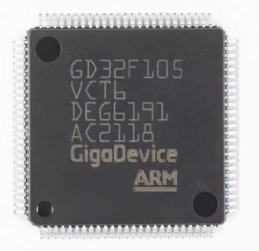
Common Issues with the GD32F105VCT6 Microcontroller
The GD32F105VCT6 is a Power ful microcontroller from GigaDevice, widely used in embedded systems for a variety of applications, including industrial control, automation, consumer electronics, and more. As with any sophisticated device, users may encounter several issues during development or deployment. The following are some of the most common problems faced when working with the GD32F105VCT6, along with effective troubleshooting strategies.
1. Power Supply Problems
Symptoms:
Power supply issues are some of the most common problems in embedded system development. If the GD32F105VCT6 does not power on or operates erratically, it's often due to problems in the power supply. Common symptoms include:
The microcontroller does not power up.
The system resets unexpectedly.
The device fails to respond to inputs or peripherals.
Troubleshooting Solutions:
Check Voltage Levels: The GD32F105VCT6 operates on a 3.3V core voltage, and the supply voltage should fall within the 2.4V to 3.6V range for proper operation. Use a multimeter or oscilloscope to verify that the supply voltage is within this range.
Verify Power Integrity: Ensure that the power supply is stable and has minimal noise. Power surges or spikes can cause unpredictable behavior or even damage the microcontroller.
Inspect Power Decoupling capacitor s: Place appropriate decoupling Capacitors close to the power pins of the microcontroller to filter noise and ensure stable power delivery.
Check for Overheating: Overheating can cause the system to reset. Ensure that the microcontroller is not subjected to high temperatures and that heat dissipation measures (like proper PCB layout and thermal vias) are in place.
2. Programming and Debugging Failures
Symptoms:
Developers may encounter problems when programming the GD32F105VCT6 or during debugging, preventing successful firmware deployment or halting in the middle of code execution. This can be particularly frustrating for embedded system development.
Troubleshooting Solutions:
Check Connections: Ensure that the programmer/debugger is properly connected to the microcontroller. Double-check the JTAG or SWD (Serial Wire Debug) connections, as poor connections can result in Communication failure.
Verify Bootloader Settings: The GD32F105VCT6 has a built-in bootloader that can affect the programming process. Make sure the bootloader settings are configured correctly (e.g., boot from Flash, not from RAM).
Reset the Microcontroller: Sometimes, a simple reset can solve programming issues. Use the NRST pin to perform a hardware reset.
Update Firmware and Software Tools: Ensure that the programming tool, such as the GD32 Flash Programmer or another compatible software, is up-to-date. Outdated tools can cause compatibility issues.
Check for Breakpoints and Watchdog Timers: Ensure that no breakpoints are set incorrectly in the code, and verify that the watchdog timer is not causing unexpected resets.
3. Clock Configuration Issues
Symptoms:
Incorrect clock settings can cause a variety of problems, including system instability, communication failure, and erratic peripheral behavior. The GD32F105VCT6 features multiple clock sources, and improper configuration can lead to performance degradation or complete malfunction.
Troubleshooting Solutions:
Verify Clock Source and PLL Settings: Ensure that the clock source and phase-locked loop (PLL) settings are correctly configured in the system initialization code. Using the wrong clock source or incorrect PLL multiplier can lead to incorrect CPU clock speeds or timing issues.
Check External Crystal Oscillator: If using an external crystal oscillator (HSE), ensure that the crystal is properly selected for the required frequency and that the oscillator circuit is correctly designed. Oscillator failures are a common cause of clock issues.
Use the Internal RC Oscillator (HSI): If the external crystal oscillator fails, you can switch to the internal RC oscillator for testing purposes to rule out external oscillator problems.
Verify Clock Output Pins: If using external peripherals that rely on specific clock signals (e.g., UART or SPI), check the clock output pins to make sure they are properly configured and providing the correct clock signal.
4. Peripheral Communication Issues
Symptoms:
Many embedded systems rely on peripheral devices (e.g., sensors, displays, motor drivers, etc.) communicating with the microcontroller via standard communication protocols like UART, SPI, or I2C. Problems with these communication channels can result in peripheral devices not being recognized or not functioning correctly.
Troubleshooting Solutions:
Check Protocol Configurations: Verify that the communication protocols (e.g., baud rate for UART, clock speed for SPI) are correctly configured. Mismatched baud rates or clock speeds can cause communication errors.
Inspect Pin Connections: Double-check the physical connections between the microcontroller and the peripheral devices. Ensure that the correct pins are used for the communication protocol (e.g., TX/RX for UART, SDA/SCL for I2C).
Use Logic Analyzer or Oscilloscope: If communication issues persist, use a logic analyzer or oscilloscope to monitor the signals on the communication lines. This can help identify signal integrity problems, timing issues, or missing signals.
Verify Peripheral Power and Ground Connections: Ensure that all connected peripherals are powered correctly and share a common ground with the microcontroller. Lack of proper grounding can lead to communication problems.
5. Firmware Bugs and Software Development Issues
Symptoms:
Firmware bugs, such as logic errors, infinite loops, and Memory corruption, are common issues that arise during software development. These bugs can cause the microcontroller to behave unpredictably or even freeze.
Troubleshooting Solutions:
Use Debugging Tools: Leverage the SWD or JTAG debugging features of the GD32F105VCT6 to set breakpoints, step through code, and inspect variable values in real-time. This can help isolate the problem quickly.
Check Memory Allocation: Ensure that dynamic memory allocation (heap and stack) is properly managed. Stack overflow or improper memory usage can lead to crashes or unpredictable behavior.
Run Diagnostics: Implement diagnostic routines in the firmware to check for unexpected behavior or hardware faults. This can help pinpoint areas of the code that need attention.
Review Interrupts and Priority Levels: Incorrect interrupt handling can lead to missed interrupts, priority inversion, or system instability. Make sure that interrupt service routines (ISRs) are correctly implemented and that the interrupt priorities are set appropriately.
Advanced Troubleshooting Techniques and Best Practices for the GD32F105VCT6
In this section, we dive deeper into more advanced troubleshooting methods and best practices for the GD32F105VCT6. These techniques help developers avoid common pitfalls, optimize system performance, and ensure long-term reliability in their designs.
6. PCB Layout Issues
Symptoms:
Faulty PCB layout can lead to various hardware issues such as signal integrity problems, noise, and power delivery issues. Common symptoms of PCB layout problems include erratic behavior, unreliable communication, and random resets.
Troubleshooting Solutions:
Minimize Trace Lengths for High-Speed Signals: Keep the traces for high-speed signals (e.g., clock, SPI) as short as possible. Long traces can introduce noise and signal degradation, leading to communication problems.
Place Decoupling Capacitors Close to the Microcontroller: Place decoupling capacitors as close as possible to the power pins of the GD32F105VCT6. This reduces the effects of power noise and improves overall stability.
Use Ground Planes: A solid ground plane on the PCB helps minimize ground bounce and ensures stable operation. Ensure that the ground plane is continuous and free of interruptions.
Careful Routing of Power and Signal Paths: Make sure to separate high-current paths (e.g., Vcc, ground) from signal traces. Power rails should be wide enough to handle the required current without excessive voltage drops.
7. Handling Overvoltage and ESD Protection
Symptoms:
Overvoltage and electrostatic discharge (ESD) can damage the microcontroller and surrounding components. If you notice intermittent issues or permanent failures in the hardware, this could be a result of overvoltage or ESD damage.
Troubleshooting Solutions:
Use Proper Voltage Regulation: Ensure that your power supply is regulated to the correct voltage for the GD32F105VCT6 (typically 3.3V). Use voltage regulators and protect the microcontroller against voltage spikes or drops.
Implement ESD Protection: Use ESD protection diodes on all I/O pins to prevent damage from electrostatic discharges. Consider using TVS (transient voltage suppression) diodes or resistors to limit current spikes on sensitive lines.
Use Proper Grounding Techniques: Proper grounding techniques, such as the use of ground planes and common ground points, can help minimize the risk of ESD and reduce noise coupling.
8. Optimizing Power Consumption
Symptoms:
Excessive power consumption is a concern, particularly in battery-powered embedded systems. High power usage can reduce battery life and lead to heat buildup.
Troubleshooting Solutions:
Enable Sleep Modes: Take advantage of the low-power sleep modes available in the GD32F105VCT6. Put the microcontroller to sleep when it is idle to conserve power.
Disable Unused Peripherals: Turn off unused peripherals (e.g., UART, ADC) to minimize power consumption.
Optimize Clock and Voltage Scaling: Use dynamic voltage and frequency scaling to adjust the power consumption based on the system’s processing needs. Consider using lower-frequency clock sources when full performance is not required.
Conclusion
The GD32F105VCT6 is a versatile and powerful microcontroller that offers significant potential for embedded system applications. However, like any complex device, it requires careful attention during design, programming, and troubleshooting. By following the tips and solutions provided in this article, you can address common issues related to power supply, clock configuration, debugging, peripheral communication, and software development.
By optimizing your PCB layout, taking precautions against overvoltage and ESD, and employing power-saving techniques, you can ensure the long-term stability and reliability of your system.
Whether you’re a seasoned embedded systems engineer or just starting with the GD32F105VCT6, this guide will help you navigate through common troubleshooting scenarios with confidence.
If you are looking for more information on commonly used Electronic Components Models or about Electronic Components Product Catalog datasheets, compile all purchasing and CAD information into one place.
Partnering with an electronic components supplier sets your team up for success, ensuring the design, production, and procurement processes are quality and error-free.


