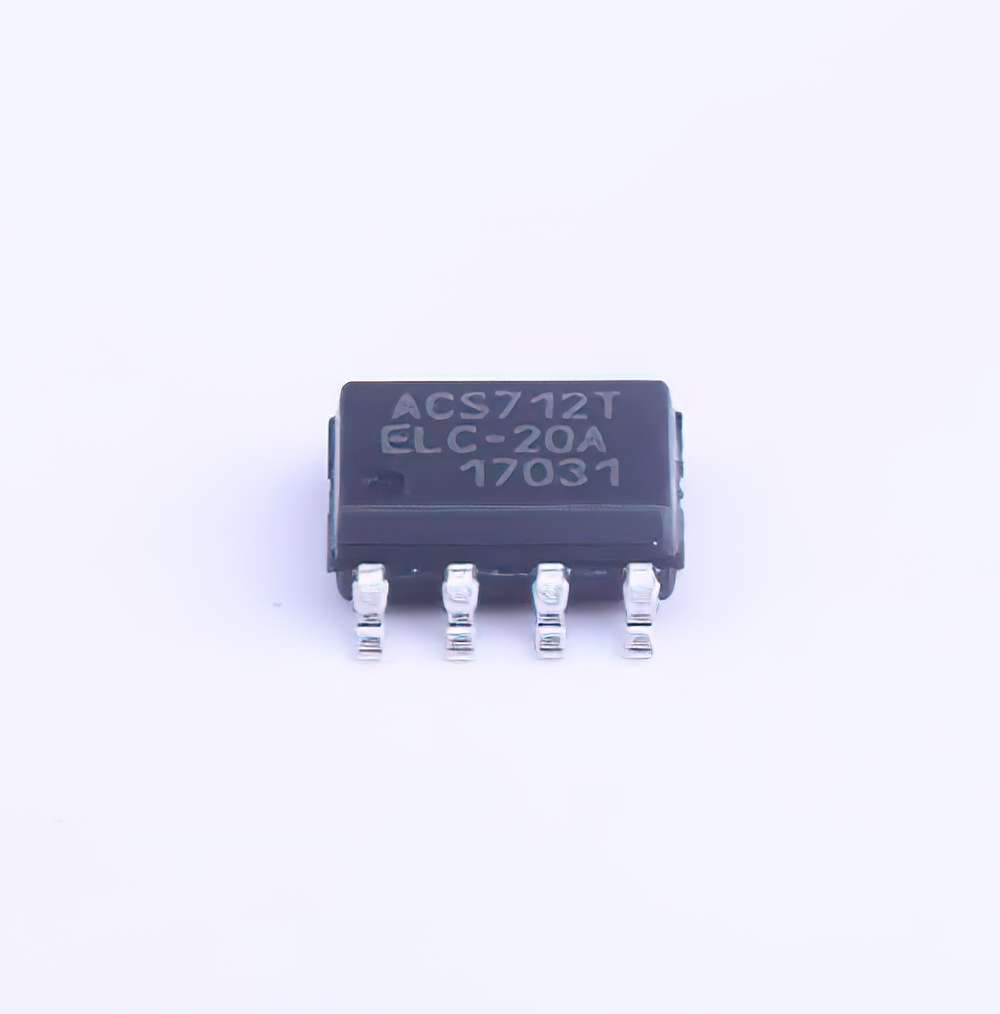
Common Issues with the ACS712ELCTR-20A-T and Their Solutions
The ACS712ELCTR-20A-T current Sensor , designed for precise and reliable current measurement, is widely used in applications like Power monitoring, load detection, and current sensing in microcontroller-based projects. However, like all electronic components, it can experience issues that hinder its performance. In this section, we’ll explore some common problems encountered when using the ACS712ELCTR-20A-T and provide practical solutions to help resolve these issues.
1. Incorrect Output Voltage
One of the most frequent issues with the ACS712ELCTR-20A-T is incorrect output voltage. Since the sensor is designed to provide a voltage output proportional to the measured current, incorrect readings often indicate that something is wrong with the setup.
Cause:
The main cause of incorrect output voltage can be related to improper calibration or wiring issues. The ACS712 outputs a voltage between 0V and 5V, where 2.5V represents zero current. If the sensor is not properly connected, or if there's an error in the calibration, the output voltage may not reflect the correct current.
Solution:
Ensure that the sensor’s VCC and GND pins are properly connected to the power supply and ground, respectively. Check that the output pin is properly connected to the ADC (Analog-to-Digital Converter) of your microcontroller. If the sensor is providing readings that are offset (e.g., a voltage that is not centered around 2.5V at zero current), you may need to recalibrate the sensor. Recalibration can often be done by adjusting your software to account for any offset voltage in your measurements.
Additionally, check if the sensor is supplied with the correct voltage, which should be between 4.5V and 5.5V. Power supply issues can also lead to inaccurate readings.
2. Noise and Instability in Readings
Another common issue when using the ACS712 is noisy or unstable readings. The sensor can sometimes output fluctuating values even when the current being measured is steady.
Cause:
The noise in readings can often be attributed to power supply instability, electromagnetic interference ( EMI ), or insufficient filtering in the sensor’s output signal. The ACS712 is highly sensitive, and any external noise in the circuit can affect its performance.
Solution:
To reduce noise, you can add capacitor s between the sensor’s VCC and GND pins (typically a 0.1µF capacitor) to help filter out high-frequency noise. Also, placing a low-pass filter on the output signal can smooth out fluctuations. For more sensitive measurements, use proper shielding and ensure that the sensor's wires are kept away from high-current carrying conductors that may induce electromagnetic interference.
3. Incorrect Current Sensing Range
The ACS712ELCTR-20A-T has a fixed current sensing range of ±20A, with a sensitivity of 185mV per amp. However, users might find that the sensor is not providing the expected results when measuring currents that are out of its range.
Cause:
If the current flowing through the sensor exceeds or falls below its rated range, the output may saturate, leading to incorrect readings or an inability to detect current accurately. This can occur in circuits where high currents are present or in cases where the sensor is not suitable for the specific range of currents being measured.
Solution:
Before using the ACS712, ensure that the sensor is rated for the expected current. If you are measuring currents beyond the sensor's maximum rating of ±20A, you will need to consider a different model with a higher current range or use a current shunt resistor and a differential amplifier.
If the current is too small, ensure that your ADC has sufficient resolution to detect small voltage variations. Otherwise, you may need to amplify the signal from the ACS712 before passing it to your microcontroller.
4. Zero Current Offset (Bias Issue)
A zero current offset or bias is another common issue faced when using the ACS712ELCTR-20A-T. When no current is flowing through the sensor, the output voltage should be 2.5V (assuming a 5V supply). However, if the sensor's output is significantly different from this baseline, it could indicate a problem.
Cause:
The zero-current offset could be caused by manufacturing tolerances, improper wiring, or interference from other components in the circuit. The sensor’s internal circuitry may also be affected by power fluctuations or grounding issues, which can introduce an offset voltage.
Solution:
To address this, ensure that the sensor is properly powered and that the ground of the sensor and the microcontroller are shared. In some cases, performing a software calibration by subtracting the measured offset can help correct this issue. If the offset persists even after calibration, check the sensor’s power supply for stability or consider replacing the sensor if it's defective.
Advanced Troubleshooting Tips and Best Practices
Once you’ve addressed the basic issues like wiring errors, calibration, and noise interference, it’s important to take a closer look at some more advanced troubleshooting tips and best practices to ensure that your ACS712ELCTR-20A-T sensor works efficiently and accurately in your application.
1. Overcurrent Protection
If the ACS712ELCTR-20A-T is exposed to currents beyond its rated capacity, it may suffer from permanent damage. Overcurrent conditions can cause sensor malfunction, affecting the reliability of your readings.
Cause:
The sensor’s rated current is ±20A, but if the circuit experiences currents above this threshold, the sensor’s internal components may be damaged, causing inaccurate readings or complete failure.
Solution:
To prevent overcurrent issues, integrate fuses or current limiting devices into your design. This can protect the sensor from any unexpected surge in current. Additionally, you can monitor the sensor’s output voltage for abnormal readings that might indicate an overcurrent condition, such as output voltages that are near the extremes of the sensor’s range (close to 0V or 5V).
2. Temperature Effects on Sensor Accuracy
The ACS712ELCTR-20A-T, like many analog sensors, can be affected by temperature changes, leading to deviations in accuracy. High temperatures, in particular, can cause the sensor to output erroneous readings, especially if it's exposed to prolonged heat.
Cause:
The accuracy of the ACS712 is typically specified for a temperature range of -40°C to +85°C, but any temperature variation outside of this range can impact the sensor's performance.
Solution:
To mitigate temperature effects, ensure that the sensor is placed in an environment where the temperature is stable and within the operating range. If the sensor will be exposed to fluctuating temperatures, you may need to implement temperature compensation in your software. Alternatively, use a temperature sensor alongside the ACS712 to detect extreme temperature conditions and adjust the readings accordingly.
3. Proper Grounding and Shielding
Improper grounding and shielding are often overlooked causes of sensor inaccuracies. Ground loops, where multiple ground paths lead to potential differences, can distort the output signal of the ACS712.
Cause:
If the sensor’s ground is not properly tied to the ground of the microcontroller or other components, you may experience fluctuations in the output signal due to differential voltages.
Solution:
Ensure that all components share a common ground. Use a single-point ground system to avoid ground loops. Additionally, use proper shielding techniques if the sensor is operating in an environment with significant electromagnetic interference.
4. Verifying Sensor Orientation and Current Flow Direction
It’s essential to verify that the current is flowing in the proper direction through the sensor. The ACS712’s output voltage varies depending on the direction of the current flow.
Cause:
If the current flows in the wrong direction, the sensor will output a voltage that is inverted compared to the expected direction.
Solution:
Double-check the wiring and orientation of the sensor to ensure that current flows through the correct path. For unidirectional current sensing, verify that the sensor is installed with the current path aligned with its markings. This will ensure accurate current measurements and correct output polarity.
Conclusion
The ACS712ELCTR-20A-T is a versatile and reliable current sensor, but like any sensor, it requires careful attention to its setup and usage. By troubleshooting common issues such as incorrect output voltage, noise, and current sensing range problems, you can ensure that your sensor operates optimally. Advanced strategies such as proper grounding, temperature compensation, and overcurrent protection can further improve the reliability of your current sensing system. With these tips, you can maximize the performance of the ACS712ELCTR-20A-T and avoid common pitfalls.
Partnering with an electronic components supplier sets your team up for success, ensuring the design, production, and procurement processes are quality and error-free.


