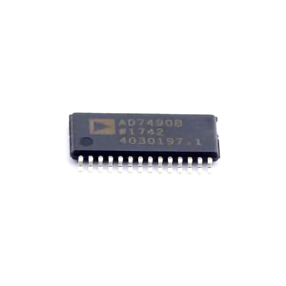
Identifying Common Issues with AD7490BRUZ and How to Resolve Them
The AD7490BRUZ is a versatile 12-bit ADC, designed for applications requiring high precision and low- Power operation. Despite its reliability, engineers and developers may face challenges when integrating or operating the AD7490BRUZ. Understanding the potential issues and implementing effective troubleshooting solutions is essential for ensuring that the device operates at its best.
1. Power Supply Instability
Problem:
One of the most common issues faced when using the AD7490BRUZ is related to power supply instability. ADCs like the AD7490BRUZ require a stable and clean supply voltage to function optimally. Fluctuations in power supply can cause inaccurate conversions or erratic behavior, including noise or unexpected output readings.
Solution:
Check the Power Supply Voltage: The AD7490BRUZ operates with a voltage range of 2.7V to 5.5V. Ensure that the supply voltage is within this range and is regulated.
Use Decoupling capacitor s: To reduce noise and power supply fluctuations, use decoupling capacitors (typically 0.1µF and 10µF) close to the power pins (VDD and VSS) of the ADC. This helps filter high-frequency noise and maintain a stable power supply.
Stabilize the Grounding: Ensure that the ground plane is continuous and has minimal impedance. A poor ground connection can introduce noise into the signal, causing inaccuracies in conversion.
2. Incorrect Clock Source or Timing Issues
Problem:
Another frequent issue arises from incorrect clocking, which can cause data synchronization problems or prevent the ADC from properly sampling and converting the input signal. Timing issues may lead to the wrong conversion results, missing data, or Communication errors.
Solution:
Verify the Clock Source: The AD7490BRUZ uses an external clock for its operation. Ensure that the clock source is accurate and within the required frequency range (1MHz to 5MHz for normal operation).
Check Timing Diagrams: Consult the AD7490BRUZ datasheet to ensure that the timing requirements are met for the ADC’s inputs, control signals, and data outputs. Timing violations can result in erroneous conversions or data misalignment.
Use a Stable Clock Generator: To ensure that the clock signal is stable, use a high-quality crystal oscillator or clock generator with minimal jitter. Jitter can degrade the performance of the ADC, leading to errors in data conversion.
3. Signal Integrity Issues
Problem:
Signal integrity is critical when working with ADCs, and the AD7490BRUZ is no exception. Poor signal quality on the input pin can cause incorrect or noisy conversions, affecting the accuracy of the data output. External noise sources, improper PCB layout, or long signal traces can contribute to this problem.
Solution:
Minimize Input Signal Noise: Ensure that the input signal is clean and within the ADC's input voltage range. Use proper filtering techniques such as low-pass filters to remove high-frequency noise before the signal reaches the ADC input.
Proper PCB Layout: Follow the recommended PCB layout guidelines provided in the datasheet. Ensure that analog and digital ground planes are separate to minimize noise coupling. Use a dedicated analog ground for the ADC and connect it to the digital ground at a single point (star grounding).
Keep Traces Short: To minimize noise pickup and signal degradation, keep analog signal traces as short as possible. Avoid running analog traces near high-speed digital lines or power traces.
4. Analog Input Range Problems
Problem:
The AD7490BRUZ has a limited input voltage range, typically 0 to VREF (where VREF is the reference voltage). If the input voltage exceeds this range, the ADC will not convert the signal correctly, and you may observe saturation or clipping at the output.
Solution:
Match Input Voltage to the ADC’s Range: Ensure that the input signal stays within the ADC’s input range. Use a voltage divider or amplifier to scale down the input signal if it exceeds the ADC’s input range.
Adjust the Reference Voltage: The AD7490BRUZ’s reference voltage (VREF) determines the input range. If the input signal is low, consider lowering VREF to match the input signal range. Conversely, for higher input signals, increase VREF, but ensure that it remains within the allowed voltage range.
5. Issues with Communication (SPI or I2C)
Problem:
The AD7490BRUZ communicates using the Serial Peripheral Interface (SPI), which requires proper configuration and signal integrity for reliable data transfer. Issues such as data misalignment, missing bits, or communication failure can occur if the SPI bus is not correctly configured or if there are problems with the clock, chip select, or data lines.
Solution:
Check SPI Configuration: Ensure that the SPI settings (clock polarity, clock phase, bit order, etc.) match the AD7490BRUZ's requirements. For example, the clock polarity should be set correctly to ensure proper synchronization between the master and slave devices.
Ensure Proper Chip Select (CS) Management : The chip select line should be held low during communication and properly deasserted when the conversion is complete. If the CS line is not managed correctly, it can cause erratic behavior or missed conversions.
Inspect SPI Signal Quality: Check for signal integrity issues on the SPI lines. High-frequency noise, crosstalk, or long trace lengths can cause data corruption. Use proper PCB routing techniques, such as using controlled impedance traces and minimizing the distance between the microcontroller and the AD7490BRUZ.
Advanced Troubleshooting and Preventative Solutions for the AD7490BRUZ
After addressing common issues, it's important to dive deeper into advanced troubleshooting techniques and preventative measures that can help mitigate potential problems when working with the AD7490BRUZ. Understanding how to optimize performance, ensure reliability, and avoid long-term failures will set your designs up for success.
6. Temperature Effects on Accuracy
Problem:
Temperature changes can significantly affect the performance of analog-to-digital converters, including the AD7490BRUZ. Variations in temperature can lead to changes in the reference voltage, input bias currents, and even the internal circuitry, impacting the accuracy of the ADC conversion.
Solution:
Use a Stable Reference Voltage: Ensure that the reference voltage for the AD7490BRUZ is stable over the expected temperature range. Consider using a low-drift, temperature-compensated reference voltage source for high-precision applications.
Temperature Compensation: If your application involves a wide temperature range, consider implementing temperature compensation algorithms or using temperature sensors to monitor temperature variations and adjust the output accordingly.
Keep the ADC in a Controlled Environment: If possible, try to place the AD7490BRUZ in an environment where temperature changes are minimal, or use heat sinks or thermal management systems to maintain stable operating temperatures.
7. Analog Input Impedance Mismatch
Problem:
The impedance mismatch between the signal source and the ADC input can lead to inaccurate conversion results or slow settling times. If the signal source impedance is too high, it may prevent the ADC from properly acquiring the input signal.
Solution:
Match Impedance: Ensure that the input impedance of the AD7490BRUZ is matched to the signal source impedance. The AD7490 has an input impedance of around 10kΩ, and it’s important to ensure that the signal source impedance is low enough to allow proper signal acquisition.
Buffer the Input: If the signal source impedance is high, consider using a buffer amplifier with low output impedance to drive the ADC input. This will ensure that the ADC input voltage remains stable and accurate during sampling.
8. Calibration and Performance Optimization
Problem:
Over time, ADCs can experience slight deviations in accuracy due to factors such as aging or temperature effects. While the AD7490BRUZ is highly accurate, periodic calibration may still be necessary to maintain optimal performance.
Solution:
Perform Regular Calibration: Periodically calibrate the AD7490BRUZ to ensure that it continues to provide accurate results. This can be done using a known reference signal or by performing a self-calibration procedure, if available.
Optimize for Resolution: Depending on the application, you may want to adjust the resolution of the AD7490BRUZ. For instance, in cases where higher resolution is needed, consider using oversampling techniques or averaging multiple samples to improve the effective resolution of the ADC.
9. Power Consumption Management
Problem:
While the AD7490BRUZ is designed for low power consumption, improper power management in the surrounding circuitry can result in higher power draw than expected, which may cause system instability or reduced battery life in portable applications.
Solution:
Use Sleep Mode: The AD7490BRUZ features a low-power sleep mode that can be activated when the ADC is not actively converting data. By utilizing this mode effectively, you can reduce the overall power consumption of your system.
Optimize Clocking: Ensure that the clock is only running when necessary. Reducing clock frequency during periods of low activity can help extend the battery life in portable applications.
10. Final Checks Before Deployment
Problem:
Before deploying a system that relies on the AD7490BRUZ, it is crucial to perform a series of final checks to ensure that all potential issues have been addressed.
Solution:
Conduct Functional Testing: Run functional tests on the ADC to verify that it operates as expected in all conditions, including variations in temperature, power supply, and signal quality.
Check for Overvoltage or Undervoltage Conditions: Ensure that all input voltages, clock signals, and supply voltages stay within the recommended operating ranges to avoid damaging the device or causing incorrect conversions.
By following these troubleshooting steps and best practices, engineers can effectively address common issues and optimize the performance of the AD7490BRUZ in their applications. Proper understanding, careful design, and vigilant testing are key to ensuring the reliability and accuracy of this powerful ADC in real-world environments.
If you are looking for more information on commonly used Electronic Components Models or about Electronic Components Product Catalog datasheets, compile all purchasing and CAD information into one place.
Partnering with an electronic components supplier sets your team up for success, ensuring the design, production, and procurement processes are quality and error-free.


