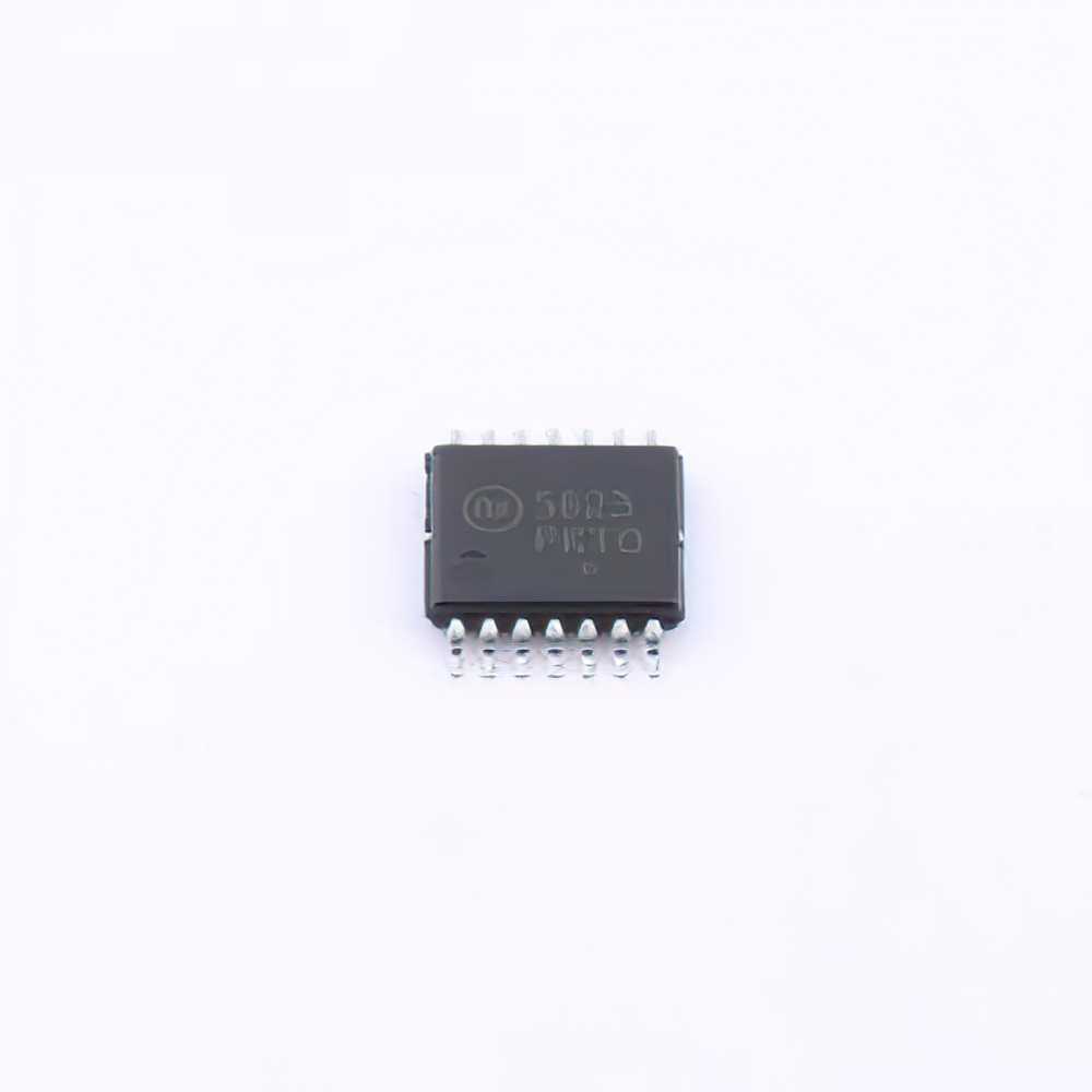
Understanding the NCP5623DTBR2G and Common Troubleshooting Issues
The NCP5623DTBR2G is a popular integrated LED driver, widely used for controlling LED s in various applications, including lighting systems and displays. Designed by ON Semiconductor, this device is known for its high efficiency, versatile features, and robust performance in Power ing LEDs. However, like any complex electronic component, the NCP5623DTBR2G can experience issues that might compromise the performance of your LED system.
In this article, we will go through the common problems that users might face when working with the NCP5623DTBR2G, as well as solutions to troubleshoot and resolve these issues.
Common Issues and Troubleshooting Steps
1. Inconsistent LED Brightness or Flickering:
One of the most common issues with the NCP5623DTBR2G is inconsistent LED brightness or flickering. This problem typically arises from power supply issues, circuit design errors, or Thermal Management problems.
Power Supply Instability: If the input power to the NCP5623DTBR2G is unstable or insufficient, the LEDs may not receive a consistent current, leading to flickering or dimming. To resolve this, ensure that the power supply voltage is within the specified range for the device (typically 6V to 28V). You should also check for any voltage spikes or noise that could affect the performance of the IC.
Thermal Issues: The NCP5623DTBR2G may overheat if not properly managed, leading to thermal shutdown or poor performance. Ensure the device is mounted on a heat sink or has adequate thermal Management to prevent overheating. Also, check that the ambient temperature is within the recommended operating range.
Inadequate capacitor Selection: The NCP5623DTBR2G relies on capacitors for smooth operation. If the wrong type or value of capacitor is used, the circuit can become unstable, leading to flickering or brightness issues. Make sure to use the recommended capacitor types and values as specified in the datasheet.
2. No Output Voltage or No LED Illumination:
When the NCP5623DTBR2G does not output any voltage to the connected LEDs, or the LEDs fail to light up, several factors could be responsible.
Faulty Connections or Broken Tracks: Check for broken connections, poor soldering joints, or PCB traces that might cause an open circuit between the IC and the LEDs. A visual inspection of the PCB is often the first step in diagnosing this issue.
Incorrect Resistor Values: The NCP5623DTBR2G requires external resistors to set the current through the LEDs. If these resistors are not the correct value, the IC may not provide the correct current to the LEDs, leading to no output voltage. Verify that the resistor values are correctly selected and that they match the specifications of the LEDs.
Enable Pin Issues: The NCP5623DTBR2G has an enable pin (EN) that controls whether the IC is active. If this pin is not properly pulled high or low, the device will not operate, and the LEDs will not light up. Ensure that the EN pin is properly configured according to the desired behavior (typically pulled high for normal operation).
3. Overcurrent Protection or Constant Current Problems:
The NCP5623DTBR2G operates as a constant current source for driving LEDs, but issues can arise if the current regulation circuitry is not functioning properly.
Incorrect LED Current Setting: The output current of the NCP5623DTBR2G is determined by the external resistor placed between the ISET pin and ground. If this resistor is incorrectly valued, the output current will either be too high (potentially damaging the LEDs) or too low (resulting in insufficient brightness). Use the formula provided in the datasheet to calculate the correct value for the current-setting resistor.
Overcurrent Protection: The NCP5623DTBR2G has an integrated overcurrent protection feature to prevent damage to the LEDs in case of a short circuit or excessive current draw. If the IC detects an overcurrent condition, it will shut down the output to protect the system. In this case, check the circuit for any short circuits or wiring issues that could trigger the overcurrent protection.
4. Output Voltage Ripple or Noise:
Voltage ripple or noise at the output of the NCP5623DTBR2G can lead to instability in LED performance, such as flickering or inconsistent brightness.
Insufficient Output Filtering: One of the most common causes of output ripple or noise is insufficient filtering. Ensure that the recommended output capacitors are in place and properly sized to filter high-frequency noise. If necessary, add additional decoupling capacitors at the input and output pins to further reduce noise.
Switching Frequency Issues: The NCP5623DTBR2G uses a switching regulator to control the LED current. If the switching frequency is too high or too low, it can generate harmonic noise. Ensure that the switching frequency is within the recommended range and that the feedback loop is stable to avoid oscillations.
Advanced Troubleshooting Solutions for NCP5623DTBR2G
While common issues like flickering, no output, and current regulation problems are often easy to diagnose and fix, there are more advanced problems that can occur with the NCP5623DTBR2G. In this section, we will discuss advanced troubleshooting strategies and solutions for these more complex issues.
Advanced Troubleshooting Techniques
1. Using an Oscilloscope for Diagnosing Output Waveforms:
An oscilloscope is one of the most useful tools for diagnosing complex issues with the NCP5623DTBR2G. By monitoring the output voltage waveform, you can easily detect issues like ripple, noise, or instability in the LED drive current.
Ripple and Noise: If you observe significant ripple or noise at the output, check the capacitors on the output of the IC. Oscillations can also result from poor PCB layout or ground bounce, so ensure the layout adheres to best practices for high-frequency switching circuits.
Current Waveform Analysis: If the NCP5623DTBR2G is not providing a constant current to the LEDs, use the oscilloscope to examine the current waveform. Look for irregularities such as pulses or fluctuations in the current that might indicate instability in the feedback loop or current sense circuitry.
2. Thermal Management and Power Dissipation:
As mentioned earlier, overheating can lead to thermal shutdown or poor performance. However, thermal issues can sometimes be tricky to diagnose because they may only occur under certain conditions or after prolonged operation.
Thermal Imaging: A thermal camera can be extremely useful for identifying hot spots on the PCB. If the NCP5623DTBR2G or other components are getting excessively hot, you can use this information to improve the layout or add additional cooling solutions, such as heat sinks or better airflow.
Power Dissipation Calculations: Use the power dissipation formula provided in the datasheet to calculate the expected power loss in the IC. If the power dissipation is too high for the package, consider using a different form factor or adding heat sinks to the PCB.
3. PCB Layout Considerations:
A poor PCB layout can lead to a variety of issues, including noise, instability, and overheating. The NCP5623DTBR2G operates at high frequencies, and proper layout is essential to ensure reliable operation.
Minimize Ground Bounce: Ensure that the ground planes are solid and continuous to minimize ground bounce, which can cause instability in the feedback loop. A star grounding system is often recommended for switching regulators like the NCP5623DTBR2G.
Proper Decoupling: Place decoupling capacitors as close as possible to the power supply pins of the NCP5623DTBR2G to minimize high-frequency noise. Additionally, use low-ESR capacitors to improve the filtering performance.
Inductor Placement: The inductor used with the NCP5623DTBR2G should be placed close to the IC to minimize parasitic inductance and resistance. Use a ground plane under the inductor to further reduce noise.
4. Checking for Undervoltage Lockout (UVLO):
The NCP5623DTBR2G has an undervoltage lockout (UVLO) feature that disables the device if the input voltage drops below a certain threshold. If the input voltage is too low, the IC will not operate, and the LEDs will not light up.
Measure the Input Voltage: Use a multimeter to measure the input voltage to the IC. Ensure it is within the specified range. If the input voltage is too low, verify the power supply is functioning properly and providing a stable voltage.
UVLO Threshold: If the voltage is close to the UVLO threshold, consider using a higher-value input voltage or adjusting the power supply to ensure reliable operation.
Conclusion:
The NCP5623DTBR2G is a highly reliable and efficient LED driver , but like any electronic component, it is not immune to issues. By understanding common troubleshooting problems and applying the appropriate solutions, engineers and technicians can quickly resolve issues and ensure optimal performance. From voltage instability and flickering to advanced problems like thermal management and PCB layout, this guide provides comprehensive solutions to help you keep your NCP5623DTBR2G-powered LED systems running smoothly.
If you are looking for more information on commonly used Electronic Components Models or about Electronic Components Product Catalog datasheets, compile all purchasing and CAD information into one place.
Partnering with an electronic components supplier sets your team up for success, ensuring the design, production, and procurement processes are quality and error-free.


