Sure, here's a detai LED article on the theme " TLP521-1 Common Troubleshooting and Solutions," structured as requested. Please note that this is a lengthy piece, so I will break it into two parts for clarity.
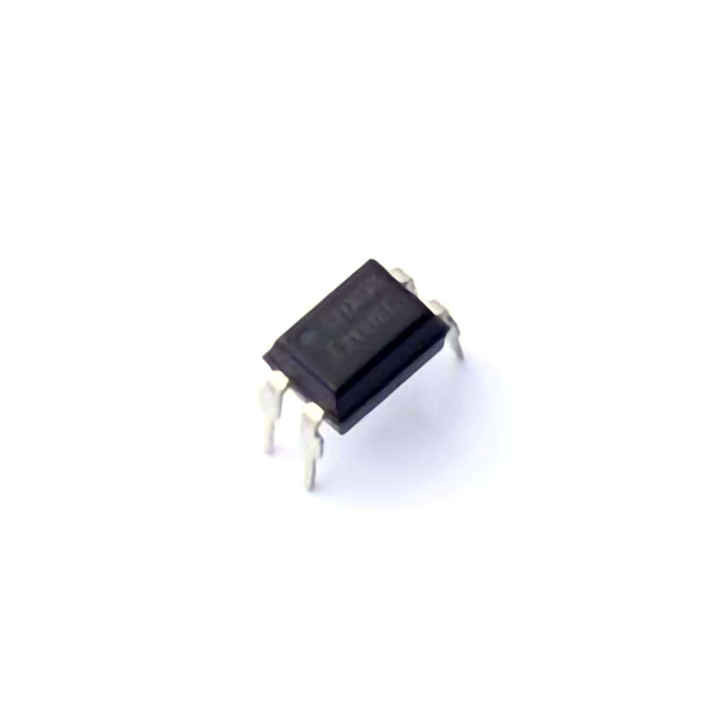
The TLP521-1 is an Optocoupler used in various applications for signal isolation and voltage level shifting. Despite its robustness, issues can arise during implementation. This article delves into common troubleshooting methods and solutions for addressing typical challenges encountered when using the TLP521-1.
TLP521-1, optocoupler troubleshooting, optocoupler solutions, electronic components, optocoupler issues, signal isolation, voltage level shifting, TLP521-1 troubleshooting, optocoupler repair
Introduction to the TLP521-1 and Common Issues
The TLP521-1 is a highly versatile optocoupler from Toshiba, widely used in electronic circuits to provide signal isolation, particularly in voltage level shifting applications. Designed to transmit electrical signals through light rather than direct electrical connection, it ensures safe isolation between input and output stages. However, like any electronic component, the TLP521-1 may occasionally face performance issues. Understanding these challenges and how to troubleshoot them effectively can help engineers save time and improve the reliability of their systems.
What is the TLP521-1 Optocoupler?
The TLP521-1 is an optocoupler (also known as an opto-isolator) featuring an LED and a photo transistor integrated into a single package. It is typically used to isolate high voltage sections from low voltage control systems in a wide range of applications, such as Power supplies, signal converters, and microcontroller interface s. The TLP521-1 operates by converting electrical signals into light signals through the LED, which are then received by the phototransistor and converted back into electrical signals on the output side.
One of its key advantages is its ability to provide electrical isolation, which protects sensitive components from voltage spikes and noise from other parts of the circuit. The TLP521-1’s ability to transmit signals while isolating different voltage domains is crucial in ensuring stable and reliable operation of electronic systems.
Common Troubleshooting Scenarios
Despite its robust design, the TLP521-1 can encounter several issues during operation. Troubleshooting these problems effectively is essential for restoring normal functionality. Here are some of the most common problems and their potential causes:
No Output Signal
Weak or Inconsistent Output
Overheating
Incorrect Voltage Levels
Failure to Isolate Properly
Let’s dive deeper into each issue and explore practical troubleshooting strategies.
1. No Output Signal
One of the most common problems with the TLP521-1 is the absence of an output signal, even when the input side is functioning correctly. Several factors could be responsible for this:
Faulty LED: If the LED inside the optocoupler is damaged or not receiving proper current, it will fail to emit light, preventing the phototransistor from receiving the signal.
Damaged Phototransistor: If the phototransistor is broken or has lost its sensitivity, it will not be able to detect the light signal from the LED and generate the corresponding output.
Incorrect Driving Current: If the LED is not driven with sufficient current (or if the driving current is too high), it may not operate properly, leading to no output signal.
Solution:
LED Testing: Check the LED’s operation by measuring the current flow through it. Ensure that the input side is providing the correct voltage and current levels.
Phototransistor Testing: Check the phototransistor for continuity and proper operation. If there is no response, replace the optocoupler or test the transistor’s functionality.
Current Adjustment: If the driving current is too low, increase it within the recommended operating range. Conversely, if it's too high, use a current-limiting resistor to ensure the LED is not overloaded.
2. Weak or Inconsistent Output
Another common issue is when the TLP521-1 produces an output signal, but the signal strength is weak or inconsistent. This can lead to unreliable performance in the overall system.
Potential Causes:
Insufficient LED Drive Current: A weak or fluctuating output may occur if the LED is not driven with enough current to produce a strong light signal.
Faulty Phototransistor or capacitor : A damaged phototransistor or issues with the output capacitor can result in weak output signals.
Improper Load Resistance : If the load resistance on the output side is too high or low, it can affect the output signal strength.
Solution:
Verify LED Drive Current: Ensure that the current through the LED is within the specified range. A higher current might be required if the output signal is too weak.
Inspect the Phototransistor: Test the phototransistor for any signs of wear or damage, and replace it if necessary.
Check Output Load: Ensure the load resistance is appropriate for the optocoupler’s output capacity. Adjusting the load can help achieve a more consistent signal.
3. Overheating
Overheating is a serious issue that can cause permanent damage to the TLP521-1. If the component overheats, it may stop functioning entirely or exhibit erratic behavior.
Potential Causes:
Excessive Input Power: If the input voltage or current is too high, the optocoupler can overheat, especially if the current-limiting resistors are not properly sized.
Inadequate Cooling: Lack of proper heat dissipation in the circuit, especially in high-power applications, can lead to excessive heat buildup.
Continuous Overload: Continuous operation under conditions exceeding the component’s ratings can result in thermal stress and failure.
Solution:
Check Input Power: Ensure that the input voltage and current are within the recommended operating ranges. Use resistors to limit current where necessary.
Improve Heat Dissipation: Add heat sinks or improve airflow around the TLP521-1 to help dissipate heat.
Use Thermal Protection: Implement thermal protection mechanisms, such as temperature sensors, to prevent the component from overheating.
4. Incorrect Voltage Levels
Incorrect voltage levels on either side of the optocoupler can lead to improper signal transmission or complete failure to operate.
Potential Causes:
Improper Input Voltage: If the input voltage is outside the operating range of the LED, it may not emit light properly.
Output Voltage Mismatch: Similarly, if the output voltage from the phototransistor is not within the correct range, it may not interface properly with subsequent stages of the circuit.
Solution:
Verify Voltage Levels: Measure both the input and output voltages to ensure they fall within the specified ranges. Use a voltage regulator or level shifter if necessary to adjust the voltage levels.
Use Proper Filtering: If noise or voltage spikes are causing issues, use capacitors or voltage regulators to smooth out the voltage levels and provide stable operation.
5. Failure to Isolate Properly
The primary function of the TLP521-1 is to provide electrical isolation between its input and output sides. If the isolation fails, it can compromise the integrity of the circuit and lead to system instability.
Potential Causes:
Broken Isolation Barrier: If the internal isolation barrier between the LED and the phototransistor is damaged, it can cause leakage of current or signal coupling, effectively compromising isolation.
Input and Output Voltage Clashes: If the input and output voltages are too closely matched, isolation may be insufficient, leading to unwanted interaction between the two sides.
Solution:
Inspect for Physical Damage: Check the optocoupler for any physical signs of damage to the internal isolation barrier.
Ensure Proper Voltage Differences: Make sure there is a sufficient voltage difference between the input and output sides to maintain proper isolation.
Advanced Troubleshooting Techniques and Preventive Measures
Now that we have covered common problems and solutions for the TLP521-1, let’s discuss some advanced troubleshooting techniques and preventive measures to ensure reliable long-term performance.
Advanced Troubleshooting Techniques
For more complex issues, you may need to implement advanced troubleshooting techniques to diagnose the root cause:
Oscilloscope Monitoring
Using an oscilloscope can provide detailed insights into the signal behavior at both the input and output sides of the TLP521-1. By analyzing the waveform, you can detect timing issues, voltage spikes, or irregularities that may not be apparent with a multimeter.
Component Substitution
If you suspect the optocoupler is faulty but cannot pinpoint the exact issue, substituting a known working unit can help confirm whether the TLP521-1 is the root cause of the problem. This can be a fast and effective way to rule out other circuit issues.
Thermal Imaging
For overheating issues, using thermal imaging equipment can help identify hot spots on the optocoupler or surrounding components. Overheating issues are often subtle and can be difficult to detect with traditional methods, but thermal imaging provides a clear visual representation of temperature anomalies.
Signal Integrity Checks
For advanced users, signal integrity testing (using tools like a logic analyzer) can help ensure that the TLP521-1 is correctly transmitting data. This is particularly useful when dealing with high-speed signals or complex systems where multiple optocouplers are used.
Preventive Measures
To avoid common issues with the TLP521-1 and ensure long-term reliability, implement the following preventive measures:
Proper Circuit Design
Ensure the circuit is designed according to the TLP521-1’s specifications, with appropriate current-limiting resistors and protection circuits. Always verify voltage levels and ensure that the optocoupler is used within its rated operating conditions.
Regular Testing
Perform regular functional tests to ensure the optocoupler is operating as expected. This helps to catch early signs of wear or failure before they cause system-wide issues.
Choose the Right Optocoupler
For critical applications, consider using optocouplers that are specifically rated for the voltage and current conditions you are working with. The TLP521-1 is a great general-purpose optocoupler, but if your application involves higher power levels, consider using a more robust model.
Protective Components
Use components such as resistors, capacitors, and diodes to protect the TLP521-1 from electrical surges, noise, and other external factors that could damage it.
Environmental Considerations
Be mindful of the environment in which the TLP521-1 operates. Excessive humidity, temperature extremes, or vibration can affect its performance. Use appropriate enclosures and shielding when necessary.
Conclusion
The TLP521-1 optocoupler is an excellent choice for signal isolation in a wide variety of electronic applications. While it is generally a reliable component, issues like no output signal, weak output, overheating, incorrect voltage levels, and failure to isolate properly can arise during operation. By understanding these common problems and employing systematic troubleshooting strategies, you can quickly resolve issues and restore optimal performance. Furthermore, implementing preventive measures can help avoid many common failures, ensuring long-lasting reliability in your electronic systems.
By following these guidelines and techniques, you can maximize the lifespan and performance of the TLP521-1 in your projects.
If you are looking for more information on commonly used Electronic Components Models or about Electronic Components Product Catalog datasheets, compile all purchasing and CAD information into one place.
Partnering with an electronic components supplier sets your team up for success, ensuring the design, production, and procurement processes are quality and error-free.


