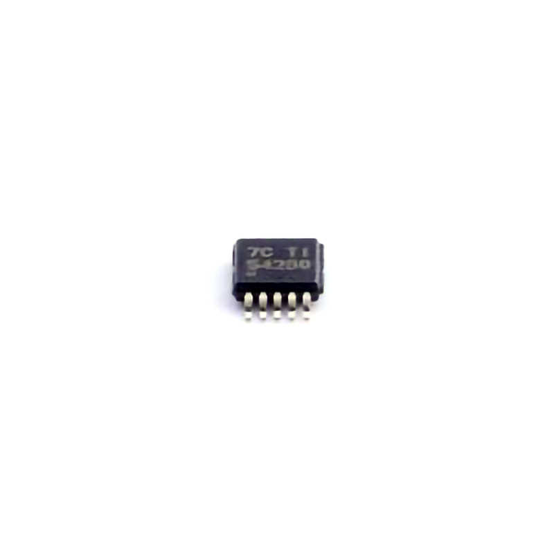
This article explores common issues and troubleshooting tips for the TPS54260DGQR , a high-performance step-down regulator, used widely in various Power Management applications. Learn how to quickly identify and resolve issues to ensure optimal efficiency, performance, and reliability in your designs.
TPS54260DGQR, Troubleshooting, Step-down Regulator, Power Management , Efficiency, Reliability, Electronics, Circuit Design, Power Supply Solutions, Power IC Issues
Understanding the TPS54260DGQR and Common Issues
The TPS54260DGQR is a versatile and efficient step-down (buck) regulator designed by Texas Instruments. It is specifically engineered to provide a stable output voltage for various applications, such as embedded systems, industrial equipment, and automotive power supplies. With an integrated solution that includes an internal power switch and optimized feedback control loop, the TPS54260 is popular for its reliability, compact design, and high efficiency.
However, despite its robustness, certain issues can arise during design, assembly, or operation. Identifying these problems early can prevent costly errors and ensure that the final product operates reliably and efficiently. In this article, we will delve into some of the most common troubleshooting challenges with the TPS54260DGQR, and provide practical solutions to address them.
1. Incorrect Output Voltage
One of the most common problems when using the TPS54260DGQR is an incorrect output voltage. This can result from several factors, including:
1.1 Incorrect Feedback Resistor Configuration
The output voltage of the TPS54260 is determined by the feedback network consisting of two resistors (R1 and R2). If these resistors are incorrectly chosen or have incorrect values, the output voltage will deviate from the expected value. To troubleshoot:
Verify the resistor values: Check the datasheet for the recommended resistor values for your desired output voltage. Ensure that the resistors are within tolerance and that the feedback loop is correctly designed.
Check for resistor drift: Over time, resistors can drift, particularly if they are subject to heat or stress. Ensure that the resistors are rated for the temperature range in which your design will operate.
1.2 Faulty Compensation Network
The compensation network helps maintain stability and good transient response in the regulator. A poorly designed or damaged compensation circuit can result in a fluctuating or incorrect output voltage. Here’s how to fix it:
Check compensation values: Ensure that the values for the compensation network (C1, R3, etc.) are in line with the recommendations from the datasheet or application notes. These values can impact loop stability and regulation performance.
Inspect for physical damage: Inspect the Capacitors and resistors in the compensation network for signs of damage such as discoloration, cracking, or shorting.
1.3 Inadequate Input Voltage
The TPS54260 requires a certain minimum input voltage to regulate properly. If the input voltage falls below the required threshold, the output voltage will drop or become unstable. To resolve this issue:
Monitor the input voltage: Use an oscilloscope or multimeter to verify that the input voltage is consistently within the required range.
Check for voltage sag: Voltage sags or dips can cause issues in the regulation loop. Ensure that your power source is capable of providing stable input voltage even under load.
2. Excessive Heat Generation
Excessive heat can damage components and lead to unstable operation. If your TPS54260 is running hot, there could be several reasons:
2.1 Overcurrent Condition
If the regulator is supplying more current than it is designed for, it can overheat. This is a common problem in power designs with high load currents. To diagnose and resolve the issue:
Check the load current: Use an ammeter to measure the current being drawn by the load. Compare this value with the TPS54260’s maximum output current rating (typically 2A).
Implement current limiting: If the load is drawing excessive current, consider adding current-limiting circuitry or ensuring that the load is within the appropriate range.
2.2 Inadequate Heat Sinking
The TPS54260DGQR is housed in a small QFN package that may not dissipate heat as efficiently as larger packages. If the device is operating at high currents or in a high ambient temperature environment, heat buildup can become a concern.
Ensure proper PCB layout: Use the recommended PCB layout in the datasheet. The TPS54260 requires a large copper area for heat dissipation, especially under high load conditions.
Use thermal vias: Incorporating thermal vias to a ground plane or a copper pour can help distribute heat more evenly across the PCB.
2.3 Poor Quality Input/Output capacitor s
The input and output capacitors play a crucial role in regulating voltage and smoothing fluctuations. Low-quality or improperly chosen capacitors can cause excessive ripple, which increases the heat generated within the device.
Verify capacitor specifications: Ensure that the capacitors meet the minimum required voltage rating and that they are of good quality (low ESR and high ripple current capacity). Choose ceramic capacitors with the correct voltage rating, and consider using bulk capacitors for added stability.
3. Noise and Ripple Issues
Power regulators like the TPS54260DGQR are sensitive to noise and ripple, which can affect the performance of the power supply and cause issues in downstream circuitry.
3.1 Inadequate Filtering
One of the primary causes of noise and ripple is insufficient filtering on the input and output sides of the regulator. Without proper decoupling, noise can couple into the regulator and affect its performance.
Add more decoupling capacitors: Adding low ESR ceramic capacitors close to the input and output pins can help filter out high-frequency noise. Follow the guidelines provided in the datasheet for recommended capacitor values and placements.
Use bulk capacitors: Larger bulk capacitors can help stabilize the output and reduce ripple, especially under dynamic load conditions.
3.2 Layout Issues
PCB layout plays a crucial role in minimizing noise and ripple. A poor layout can lead to excessive noise coupling, grounding issues, and EMI problems.
Minimize loop area: Keep the feedback loop and high-current paths as short as possible to reduce noise coupling.
Separate power and signal grounds: Ensure that the power ground and signal ground are separated to avoid interference between the noisy power circuit and sensitive signal traces.
Advanced Troubleshooting and Solutions
4. Startup and Stability Problems
Another frequent issue with the TPS54260 is trouble during startup. These can range from the regulator failing to start to instability once it has started. Common reasons for startup and stability problems include:
4.1 Soft-Start Configuration
The TPS54260 includes a soft-start feature that gradually ramps up the output voltage to reduce inrush current. If the soft-start time is too short, the regulator may not have enough time to reach stable operation before the load is applied.
Check the soft-start capacitor: Ensure that the soft-start capacitor is installed and that its value matches the recommendations in the datasheet. A larger capacitor results in a slower, smoother startup.
Adjust for load current: If your load is highly sensitive, you may need to adjust the soft-start capacitor to prevent overshoot or inrush current.
4.2 Feedback Loop Instability
Instability in the feedback loop can cause oscillations or erratic behavior in the output voltage. This could be due to poor capacitor selection or a failure in the compensation network.
Check the compensation network: Verify that the compensation components (C1, R3, etc.) match the design requirements for your application. If necessary, consult the TPS54260’s application notes or TI’s web-based tools to fine-tune these values.
4.3 Power Good Signal Issues
The TPS54260 includes a power-good (PG) signal that indicates whether the output voltage is within the specified range. If this signal is not functioning correctly, it could indicate problems with the regulator’s operation.
Verify PG pin operation: Measure the PG pin voltage using an oscilloscope. If the PG signal is not functioning properly, inspect the circuit connected to the PG pin for potential issues, such as incorrect pull-up resistor values.
5. Overvoltage and Overcurrent Protection
In some situations, the TPS54260 may enter overvoltage (OVP) or overcurrent (OCP) protection modes, causing the output voltage to drop or become unstable. These protections are designed to safeguard the regulator and connected components from damage.
5.1 Overcurrent Protection
If the load exceeds the maximum current rating of the TPS54260, it will enter an overcurrent protection mode, which can cause the output voltage to drop or oscillate.
Monitor current levels: Use an ammeter or a current-sensing circuit to ensure the load current stays within the recommended limits.
Check for short circuits: Ensure that there are no shorts in the circuit or components that could be drawing excessive current.
5.2 Overvoltage Protection
The TPS54260 may enter overvoltage protection mode if the output voltage exceeds its specified range. This can happen due to incorrect resistor settings, feedback issues, or component failure.
Check feedback loop and resistors: As mentioned earlier, ensure that the feedback resistors are set correctly and that the feedback loop is functioning properly.
Inspect for component failures: If components such as diodes, capacitors, or resistors have failed, they could be causing the overvoltage issue. Inspect these components carefully.
By understanding the common issues associated with the TPS54260DGQR and knowing how to address them effectively, you can ensure that your power supply operates reliably and efficiently. From basic configuration problems like incorrect feedback resistor settings to more complex issues like thermal management and feedback loop stability, proper troubleshooting is essential for successful implementation of this versatile step-down regulator.
In conclusion, the TPS54260DGQR is a highly efficient and reliable power solution for a wide variety of applications. By following best practices for design, assembly, and testing, and using the troubleshooting techniques discussed in this article, engineers can minimize downtime and improve the performance of their power supply systems.
Partnering with an electronic components supplier sets your team up for success, ensuring the design, production, and procurement processes are quality and error-free.

