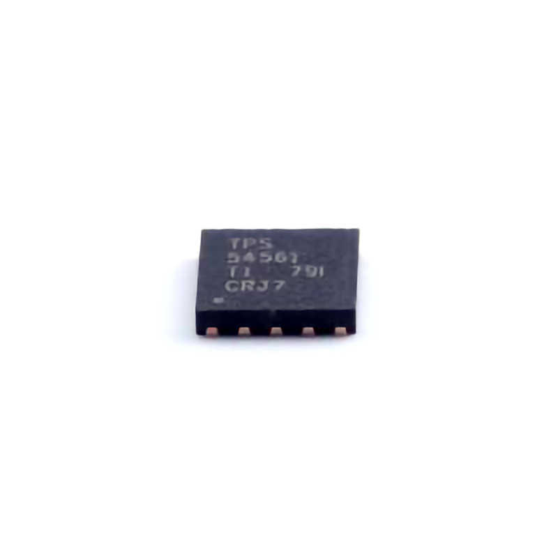
Common Troubleshooting Issues in TPS54561DPRR
The TPS54561DPRR is a highly versatile and efficient DC/DC buck converter designed for Power ing a wide range of systems, from industrial applications to consumer electronics. While it is a reliable component, users may occasionally encounter issues during operation. In this first part of our guide, we will explore some of the most common troubleshooting problems faced with the TPS54561DPRR and how to address them effectively.
1. Output Voltage Instability
One of the most common issues encountered in the operation of the TPS54561DPRR is unstable or fluctuating output voltage. This problem can manifest as voltage spikes, drops, or inconsistent voltage levels.
Causes:
Incorrect Feedback Loop Configuration: The TPS54561DPRR uses a feedback mechanism to regulate the output voltage. If the feedback loop is not properly configured or if components are faulty (e.g., resistors, capacitor s), this can result in voltage instability.
Noise Interference: Excessive noise from the input power supply or surrounding electronics can disrupt the feedback loop, leading to fluctuations in output voltage.
Faulty External Components: Capacitors or Inductors used in the design of the converter may degrade over time or be improperly selected, causing the output voltage to become unstable.
Solutions:
Check Feedback Loop Components: Ensure that the feedback resistors and capacitors are of the correct value and quality. Use low tolerance resistors and high-quality ceramic capacitors for better performance.
Use Proper Layout Design: The layout of the PCB should be optimized for low noise. Keep the power and ground planes separate, minimize loop areas for high-frequency signals, and ensure adequate grounding.
Add Filtering Capacitors: Adding additional capacitors (such as 10µF to 100µF) at the output can help reduce high-frequency noise, stabilizing the output voltage.
2. Overheating of the TPS54561DPRR
Another common issue is overheating of the TPS54561DPRR, which can lead to thermal shutdown and reduced efficiency. Overheating may cause the converter to stop functioning or become unreliable.
Causes:
Inadequate Heat Dissipation: If the TPS54561DPRR is not properly heat-sinked or if the ambient temperature is too high, the device can overheat. Additionally, poor PCB layout and insufficient copper area for heat dissipation can exacerbate the problem.
Excessive Load Current: Drawing more current than the TPS54561DPRR is rated for can cause it to overheat. The device is rated for up to 5A of continuous output current, and exceeding this value can lead to thermal stress.
Increased Power Dissipation: High input voltages and significant output current can increase the power dissipation within the device, leading to temperature rise.
Solutions:
Improve Heat Management : Ensure that the TPS54561DPRR is placed in a well-ventilated area and has adequate heat sinking. Using a larger PCB with more copper area around the device can help dissipate heat more effectively.
Reduce Input Voltage: If possible, reduce the input voltage to decrease the internal power dissipation of the converter. Alternatively, consider using a switching regulator with a lower input-to-output voltage difference.
Ensure Proper Load Current: Verify that the load connected to the converter does not exceed its maximum rated current. If higher current is required, consider using a higher-rated device or multiple converters in parallel.
3. Input Voltage Sagging
An input voltage sag, where the voltage supplied to the TPS54561DPRR drops significantly during operation, can lead to a malfunctioning converter, causing instability or even shutdown.
Causes:
Input Capacitor Issues: If the input capacitors are degraded, incorrectly sized, or missing, the input voltage may not be adequately filtered, causing voltage dips or ripple.
High Source Impedance: If the source impedance of the power supply is too high, it may not be able to maintain a stable voltage during periods of high load current.
Long or Thin Power Traces: Excessively long or thin traces from the input power supply to the converter can introduce additional Resistance and inductance, contributing to voltage sag.
Solutions:
Check Input Capacitors: Ensure that the input capacitors are of the correct value and quality. The recommended value for the input capacitor is typically around 10µF to 22µF with low ESR (Equivalent Series Resistance).
Use a Stable Power Supply: Verify that the input power supply can provide the necessary current and maintain a stable voltage. A higher-quality power supply or one with lower source impedance may be necessary.
Minimize Trace Resistance: Optimize the PCB layout to minimize the resistance of the input power traces. Use wider traces or thicker copper to reduce voltage drops.
4. No Output Voltage
If the TPS54561DPRR fails to produce any output voltage, it can be due to several reasons ranging from incorrect component selection to improper power sequencing.
Causes:
Faulty External Components: Incorrectly sized or faulty external components such as resistors, capacitors, or inductors can prevent the device from properly regulating the output voltage.
Faulty Power Sequencing: If the input voltage is applied before the enable pin (EN) is triggered, the converter may fail to start up.
Device Failure: In rare cases, the TPS54561DPRR itself may be faulty due to manufacturing defects, electrostatic discharge (ESD), or over-voltage conditions.
Solutions:
Verify Component Values: Ensure that all external components (e.g., resistors, capacitors, inductors) are properly sized according to the reference design in the datasheet.
Check Enable Pin (EN): Verify that the EN pin is receiving the correct logic signal (high or low) to enable the converter. If necessary, use an external pull-up resistor to ensure proper operation.
Check for Faults: Use an oscilloscope or multimeter to check for any signs of short circuits or open circuits in the power path. If the device is still unresponsive, consider replacing it with a new one.
Advanced Troubleshooting and Optimization for the TPS54561DPRR
In the second part of this guide, we will cover more advanced troubleshooting techniques and optimization strategies to ensure the TPS54561DPRR performs at its best, particularly in demanding applications.
5. Output Voltage Ripple and Noise
Voltage ripple and noise can significantly impact the performance of sensitive electronics powered by the TPS54561DPRR. High ripple or noise can cause instability in the powered circuit, leading to malfunction or errors.
Causes:
Insufficient Output Filtering: If the output capacitors are undersized or of poor quality, they may not adequately filter out high-frequency ripple or noise.
Inductor Saturation: If the inductor is not chosen correctly or is too small, it can saturate under load, causing increased ripple at the output.
PCB Layout Issues: A poor layout can exacerbate noise problems. Improper placement of ground planes, long signal traces, or inadequate decoupling can contribute to high ripple and noise.
Solutions:
Optimize Output Filtering: Increase the size of the output capacitors to provide better filtering. Choose high-quality low-ESR capacitors that are optimized for high-frequency operation.
Select an Appropriate Inductor: Ensure that the inductor chosen for the application has the right current rating and does not saturate at the expected load current.
Improve PCB Layout: Ensure that the layout minimizes noise coupling between high-current paths and sensitive signal traces. Use a continuous ground plane and place decoupling capacitors close to the TPS54561DPRR and other critical components.
6. Stability and Loop Compensation
The stability of the feedback loop in the TPS54561DPRR is critical to achieving optimal performance. If the loop is not properly compensated, the converter may experience oscillations, poor transient response, or instability under varying load conditions.
Causes:
Improper Compensation Network: The TPS54561DPRR requires specific compensation components (e.g., resistors and capacitors) to ensure stable operation. Incorrect values can lead to instability.
Load Transients: Sudden changes in load can cause the converter to become unstable if the loop is not adequately compensated to handle such transients.
Solutions:
Tune the Compensation Network: Refer to the datasheet for recommended compensation component values for different output voltages and load conditions. Adjust the compensation network to ensure stable operation across the expected range of operating conditions.
Use the Loop-Bandwidth Optimization: For applications requiring very high performance, you may need to optimize the loop bandwidth to improve transient response while maintaining stability.
7. Improving Efficiency
Although the TPS54561DPRR is highly efficient, there are always opportunities to improve performance, especially in power-sensitive applications. Efficiency losses can occur due to various factors such as parasitic elements, improper component selection, or suboptimal layout.
Causes:
High Conduction Losses: Excessive resistance in the power path or poorly selected components (e.g., inductors with high DCR or poor-quality MOSFETs ) can increase conduction losses.
Switching Losses: High-frequency switching can lead to losses if not carefully managed, especially in noisy or high-load environments.
Solutions:
Optimize Power Path Resistance: Use low-resistance components and ensure the PCB traces are thick and short to reduce conduction losses.
Select Low-Loss Inductors and FETs: Choose components with low resistance and high efficiency to minimize switching and conduction losses.
Use Synchronous Rectification: Ensure that the TPS54561DPRR is using synchronous rectification, which can improve efficiency by reducing power dissipation during switching.
8. EMI and Noise Mitigation
Electromagnetic interference (EMI) is a concern in many designs using switching regulators like the TPS54561DPRR. High-frequency switching can radiate noise, potentially interfering with other sensitive electronics.
Causes:
Fast Switching Transients: The fast switching transitions of the TPS54561DPRR can generate high-frequency noise that can radiate from the power traces or the switching node.
Insufficient Shielding and Grounding: Without proper shielding and grounding, the converter can emit EMI that affects nearby components.
Solutions:
Use Proper Filtering: Implement additional input and output filtering, such as ceramic capacitors and ferrite beads , to reduce high-frequency noise.
Improve Grounding and Shielding: Ensure the PCB layout includes adequate ground planes and consider adding shielding to the converter and nearby sensitive components.
Reduce Switching Frequency: In some cases, reducing the switching frequency can help reduce EMI, although this may come at the cost of efficiency.
Conclusion
Troubleshooting and optimizing the performance of the TPS54561DPRR requires a combination of careful design, proper component selection, and attention to detail in layout and operation. By following the troubleshooting steps outlined in this guide, you can identify common issues such as voltage instability, overheating, and ripple, while implementing effective solutions to address them. With the right precautions and optimizations, the TPS54561DPRR can provide reliable, efficient, and stable power for a wide range of applications.
If you are looking for more information on commonly used Electronic Components Models or about Electronic Components Product Catalog datasheets, compile all purchasing and CAD information into one place.
Partnering with an electronic components supplier sets your team up for success, ensuring the design, production, and procurement processes are quality and error-free.


