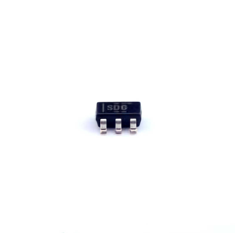
Understanding the TPS70933DBVR and Common Issues
The TPS70933DBVR is a highly efficient low dropout (LDO) voltage regulator that offers a stable output voltage with low output noise and high output current capability. Designed for low-power applications, it’s a favorite choice for many electronic systems, ranging from portable devices to complex industrial machinery. However, as with any complex electronic component, troubleshooting is often necessary when things don’t work as expected.
In this part, we’ll explore the common issues that engineers and designers encounter with the TPS70933DBVR, followed by insights into why these problems occur and the necessary steps to resolve them.
1. Output Voltage Instability
One of the most common problems reported with LDO regulators, including the TPS70933DBVR, is output voltage instability. This can manifest as voltage fluctuations or noise, which can severely affect the performance of the downstream circuits. The key factors contributing to this issue are:
Insufficient Output capacitor : The TPS70933DBVR requires a stable output capacitor to regulate the voltage correctly. If the capacitor is too small or not of the recommended type (e.g., ceramic), the regulator may fail to maintain a stable output voltage.
Capacitor Placement: The physical placement of capacitors in a circuit can significantly impact voltage regulation. Improper placement might introduce additional noise or interference, leading to instability.
Solution: Ensure that the output capacitor meets the recommended specifications (typically a 10µF ceramic capacitor). Moreover, pay attention to the layout design of your PCB to minimize parasitic inductances and reduce the impact of noise.
2. Thermal Shutdown
The TPS70933DBVR features internal thermal shutdown to protect itself from overheating. If the regulator is subjected to excessive load or poor thermal management, it may enter thermal shutdown mode, causing it to stop outputting voltage.
Solution: Ensure proper thermal dissipation in the design by using heat sinks or enhancing the PCB layout with larger copper areas around the regulator. Also, verify that the output current does not exceed the rated specifications.
3. Overcurrent Protection
The TPS70933DBVR has built-in overcurrent protection to safeguard against excessive current draw. If the load demands more current than the regulator can supply, the regulator will either reduce the output voltage or shut down altogether.
Solution: If overcurrent is suspected, check the current demand of the load and ensure it does not exceed the maximum current rating of the device. Also, ensure the power supply is capable of handling the total current required by the circuit.
4. Start-up Failures
Another issue that users sometimes experience is failure during the initial startup of the regulator. This could be due to multiple factors, including improper input voltage levels, incorrect component selection, or a malfunctioning enable signal.
Solution: Ensure that the input voltage meets the minimum requirements for the TPS70933DBVR to start up. Double-check that the enable signal (if used) is correctly configured, and that all capacitors and resistors are properly placed.
5. Excessive Noise
While the TPS70933DBVR is designed to offer low output noise, users may still encounter excessive noise or ripple on the output. This can disrupt the performance of sensitive analog circuits or signal processing systems.
Solution: Consider adding additional bypass capacitors (such as a 0.1µF capacitor) on the input and output pins to filter out high-frequency noise. Also, check the PCB layout for proper grounding and signal integrity.
Advanced Troubleshooting and Design Tips for the TPS70933DBVR
While basic troubleshooting tips can resolve many common issues, engineers often need to dive deeper into the design and operating conditions to identify more complex problems. In this part, we’ll look into advanced troubleshooting techniques, design considerations, and tips to ensure that the TPS70933DBVR operates at peak efficiency.
6. Input Voltage Drop
An unstable or insufficient input voltage can lead to issues such as voltage sag, improper regulation, or even failure of the TPS70933DBVR. If the input voltage falls below the regulator’s dropout voltage (typically 0.3V for the TPS70933DBVR), the regulator will be unable to maintain a stable output.
Solution: Monitor the input voltage to ensure it stays within the recommended operating range. If the input voltage is near the dropout limit, consider using a higher input voltage or choosing a regulator with a lower dropout voltage for your specific application.
7. PCB Layout Issues
When designing with the TPS70933DBVR, a poor PCB layout can cause many issues, from excessive noise to thermal shutdown. Proper layout and routing are crucial to ensure stable operation.
Solution: Here are some critical tips for optimizing the layout of your PCB:
Keep the traces between the regulator and the output capacitor as short as possible to minimize parasitic inductance and resistance.
Use wide traces for the input and output power paths to minimize voltage drops and reduce the impact of noise.
Place the output capacitor as close as possible to the output pin to provide optimal filtering and improve the stability of the regulator.
Use solid ground planes to provide a low-impedance path for the return currents.
8. Input Capacitor Selection
Although the TPS70933DBVR doesn’t demand an input capacitor for operation, having one is often beneficial, especially in circuits where the input supply may have high ripple or noise. An inadequate input capacitor can cause instability or worse, a failure to start up.
Solution: A 1µF ceramic capacitor placed close to the input pin is often recommended to filter any high-frequency noise. If the input supply is noisy or unstable, increasing the input capacitor value or using a bulk capacitor can further stabilize the input.
9. Load Transients
Another common problem in power systems is load transient response. This occurs when there is a sudden change in the current drawn by the load, which can momentarily cause a voltage dip or spike. The TPS70933DBVR may struggle to quickly respond to these changes if the load is highly dynamic.
Solution: To address load transients, place a bypass capacitor (e.g., 0.1µF) in parallel with the load to help absorb sudden changes in current demand. Additionally, ensure the regulator has enough output capacitance to handle sudden current demands without significant voltage deviation.
10. Feedback Loop Stability
The stability of the feedback loop is critical in any voltage regulator design. If the feedback loop is poorly designed, it can lead to oscillations, instability, or poor load regulation. This is often observed when improper compensation or wrong feedback components are used.
Solution: Ensure that the feedback resistors are selected according to the design specifications. If external compensation is required, consult the TPS70933DBVR datasheet for recommendations on component values. Pay attention to the phase margin and ensure there is adequate compensation for the load and operational conditions.
11. Using the Enable Pin
The enable pin on the TPS70933DBVR controls the regulator’s operation. If the enable signal is not correctly configured or is subject to interference, the regulator may fail to start or behave erratically.
Solution: Ensure the enable pin is properly connected to a logic signal or tied to the appropriate voltage level. For instance, pulling the enable pin high will turn on the regulator, while pulling it low will disable the output. In case of an analog control, make sure that the signal is clean and free from noise.
12. Monitoring and Diagnostics
Lastly, implementing robust monitoring and diagnostic tools can help detect and troubleshoot issues in real-time. You can use oscilloscopes to check for voltage dips or spikes, measure the ripple on the output, and monitor the regulator’s performance under various load conditions.
Solution: Integrating feedback mechanisms such as output voltage monitoring and current sensing can alert engineers to issues like overcurrent conditions, output voltage drift, or thermal problems. This early detection can prevent long-term damage and improve system reliability.
Conclusion:
The TPS70933DBVR voltage regulator is a powerful and reliable component, but like all electronic systems, it requires careful design and monitoring to operate optimally. By understanding the common issues and employing the solutions outlined in this article, engineers can ensure the regulator operates efficiently, reliably, and with minimal troubleshooting.
By taking steps such as optimizing PCB layouts, selecting proper components, and using real-time diagnostics, you can avoid most common issues and maximize the performance of your power management system. Always refer to the TPS70933DBVR datasheet for additional technical details and recommendations specific to your application.
If you are looking for more information on commonly used Electronic Components Models or about Electronic Components Product Catalog datasheets, compile all purchasing and CAD information into one place.


