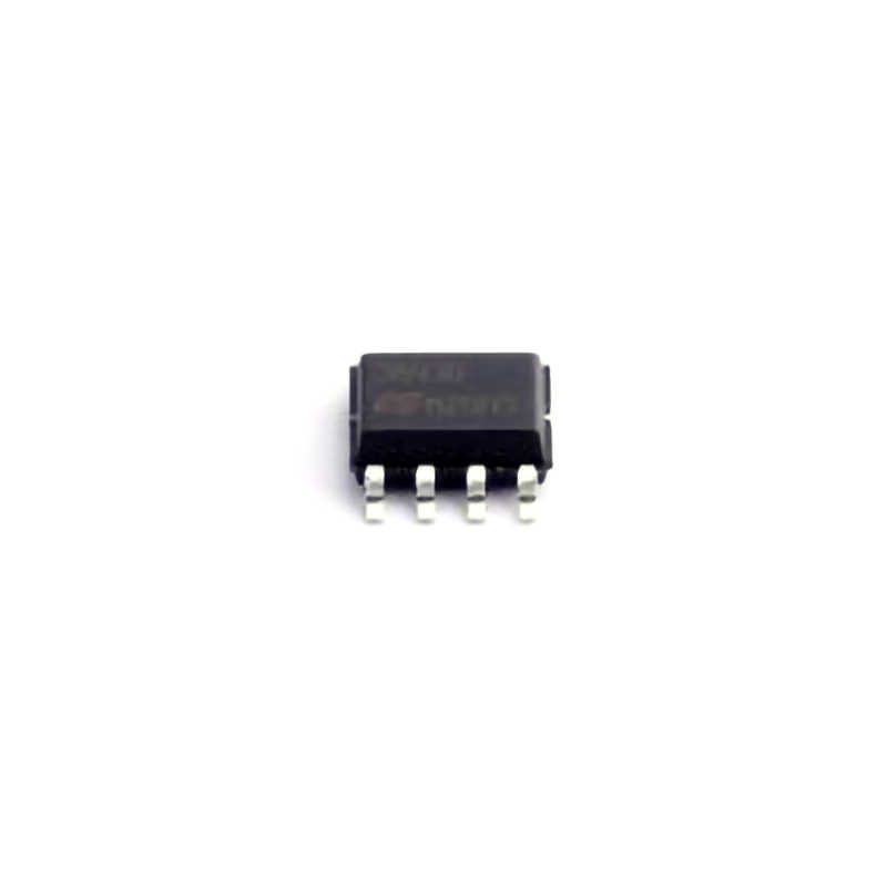
The UC3843BD1013TR is a versatile integrated circuit (IC) widely used in Power supply designs, including pulse-width modulation (PWM) controllers. This article delves into common issues faced during its usage and provides practical troubleshooting steps to ensure optimal performance. Whether you are an experienced designer or new to power electronics, this guide will help you identify, diagnose, and resolve common problems, maximizing the efficiency and longevity of your designs.
Understanding UC3843BD1013TR and Common Troubleshooting Techniques
The UC3843BD1013TR is a highly effective PWM controller widely used in power supply designs. As part of a family of integrated circuits, it is most commonly employed in controlling DC-DC converters, AC-DC adapters, and other power management applications. This IC is particularly favored for its ability to provide high performance while being energy efficient. However, like all electronics, the UC3843BD1013TR may present issues during design or operation. In this section, we’ll explore some common problems associated with this component and the initial steps for troubleshooting.
1. Poor Output Regulation
One of the most common issues when using the UC3843BD1013TR is poor output voltage regulation. This problem typically manifests as fluctuating or unstable output voltages in the power supply. There are several possible reasons for this:
Inadequate Compensation: The UC3843BD1013TR uses an external feedback loop to regulate the output voltage. If the feedback network is not properly compensated, the output voltage can become unstable, leading to poor regulation.
Faulty Components: A defective external resistor or capacitor in the feedback path can lead to inaccurate feedback, which impacts the regulation of the output.
Insufficient Input Voltage: Ensure that the input voltage is within the required range for the UC3843BD1013TR to function properly. If the input voltage is too low, it could cause the IC to operate incorrectly, affecting output regulation.
Troubleshooting Steps:
Start by verifying the compensation network. Check the resistor and capacitor values in the feedback loop, ensuring they match the recommendations in the datasheet. If necessary, adjust them based on your design requirements.
Measure the input voltage to confirm it is stable and within the specified operating range.
Inspect the power supply for any potential issues with the external components like resistors or capacitors. Use an oscilloscope to observe the behavior of the output voltage and ensure it is steady.
2. Overheating of the IC
Overheating is another common problem associated with the UC3843BD1013TR, especially under heavy loads or inefficient designs. Excessive temperature can lead to thermal shutdown, reducing the life of the IC or causing it to stop functioning altogether.
Potential Causes:
Inadequate Heat Dissipation: The IC may not have sufficient cooling or heat sinking to dissipate the generated heat.
High Output Current Demand: If the power supply is supplying a load that exceeds its rated output current, the IC can overheat due to the extra power dissipation.
Poor PCB Layout: Poor thermal management on the PCB can lead to hot spots, causing the IC to overheat.
Troubleshooting Steps:
Verify the thermal design of your PCB and ensure that the IC has proper heat sinking or thermal vias to dissipate heat efficiently.
Measure the output current and ensure it does not exceed the specifications of the IC. If necessary, adjust your design to match the current requirements of the load.
Check the temperature of the IC using an infrared thermometer. If it is excessively hot, it may require additional cooling measures or redesigning to distribute heat more evenly.
3. Erratic Switching Behavior
The UC3843BD1013TR controls the switching behavior of power supplies, and erratic switching behavior can lead to poor performance or failure of the power supply. This can be caused by several factors:
Faulty Switching Components: External components like transistor s, diodes, or inductors can cause switching anomalies if they are defective or improperly rated.
Oscillator Issues: The UC3843BD1013TR includes an internal oscillator to drive the switching cycle. If the timing components (resistors and capacitors) are incorrectly sized, the oscillator may malfunction.
Load Transients: Sudden changes in load can affect the switching frequency and stability of the IC.
Troubleshooting Steps:
Check the external components responsible for switching (e.g., MOSFETs or diodes) to ensure they are functioning correctly and rated properly for your application.
Verify the oscillator components. Use a frequency counter or oscilloscope to check that the switching frequency aligns with your design specifications.
Monitor the load conditions to ensure smooth transitions. Load transient response may need additional capacitive filtering or snubber circuits to prevent switching anomalies.
Advanced Troubleshooting and Design Optimization for UC3843BD1013TR
In the second part of this guide, we will explore more advanced troubleshooting strategies and design optimization techniques for the UC3843BD1013TR. These insights can help you enhance the performance and reliability of your power supply design, ensuring that the UC3843BD1013TR operates at its highest efficiency.
4. Input Voltage Instability
An unstable input voltage can cause the UC3843BD1013TR to malfunction, resulting in improper regulation, excessive heat, or even damage to the IC. Several factors can contribute to input voltage instability:
Power Supply Issues: If the input voltage is supplied by another power stage, any fluctuation or noise in the source could affect the performance of the UC3843BD1013TR.
Improper Filtering: If the input voltage is noisy or contains ripple, this can affect the operation of the IC, causing instability in both the feedback loop and the output.
Troubleshooting Steps:
Use an oscilloscope to measure the input voltage and observe any fluctuations or noise.
Add additional filtering capacitors (e.g., electrolytic or ceramic capacitors) to the input stage to smooth out any high-frequency ripple.
Ensure that the input voltage is within the acceptable range specified by the datasheet. Any deviations from this range may cause operational issues.
5. Overcurrent Protection Failure
The UC3843BD1013TR incorporates built-in overcurrent protection to safeguard the power supply. However, if this feature is not functioning properly, it can lead to excessive current draw, potentially damaging the IC or connected components.
Potential Causes:
Incorrect Sense Resistor: The current-sensing resistor may be incorrectly rated or improperly placed in the circuit, preventing accurate current detection.
Faulty Overcurrent Detection Circuit: If the overcurrent detection circuitry is malfunctioning, the IC may fail to respond to high current situations, leading to potential damage.
Troubleshooting Steps:
Verify the sense resistor value. Ensure it matches the specifications for your design and is placed correctly in the circuit.
Check the feedback from the current sense pin to ensure the IC is detecting current accurately.
Test the overcurrent protection mechanism by simulating overcurrent conditions and observing the IC’s response. It should shut down or limit current as needed.
6. PCB Layout Optimization
One of the most critical aspects of using the UC3843BD1013TR effectively is a well-optimized PCB layout. Poor layout design can lead to many issues, such as noise interference, power loss, and thermal hotspots.
Common Layout Problems:
Long Trace Lengths: Long traces can introduce parasitic inductances and capacitances, which negatively affect switching behavior.
Poor Grounding: A poor ground plane can cause ground loops and noise, leading to instability and inaccurate feedback.
Inadequate Component Placement: Improper placement of critical components like the current sense resistor or feedback network can degrade performance.
Design Tips:
Keep trace lengths as short as possible, especially for high-current paths.
Use a solid ground plane to reduce noise and ground loops.
Place sensitive components (such as the feedback network) away from noisy components like high-current traces or switching devices.
By following these troubleshooting steps and design optimization strategies, you can ensure that your UC3843BD1013TR-based power supply operates at peak efficiency, providing reliable and stable output for your application. Always consult the datasheet for the UC3843BD1013TR for additional specifications and recommendations tailored to your design needs.
If you are looking for more information on commonly used Electronic Components Models or about Electronic Components Product Catalog datasheets, compile all purchasing and CAD information into one place.
Partnering with an electronic components supplier sets your team up for success, ensuring the design, production, and procurement processes are quality and error-free.


