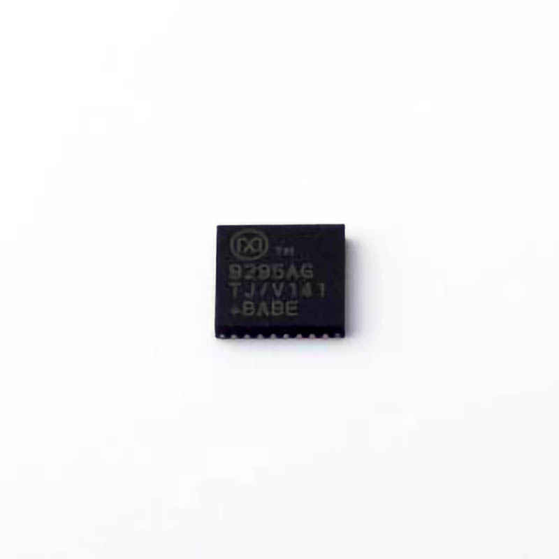
Introduction to MAX9295AGTJ/V+T and Common Issues
The MAX9295AGTJ/V+T is a robust serializer/deserializer (SerDes) designed for high-speed data Communication . It is used primarily in automotive, industrial, and surveillance systems for transmitting data between devices over long distances, often in challenging environments. The key advantage of this device is its ability to provide a high-speed, reliable data link with low latency while maintaining excellent signal integrity.
However, like any complex s EMI conductor device, users may encounter a range of issues during operation. Understanding these common problems and knowing how to troubleshoot them effectively is essential to ensuring optimal performance. This article provides a comprehensive guide to the most frequent issues with the MAX9295AGTJ/V+T and the steps you can take to diagnose and solve them.
Overview of the MAX9295AGTJ/V+T
The MAX9295AGTJ/V+T is a part of Maxim Integrated’s line of high-performance SerDes ICs, which are commonly used for transmitting high-speed data in automotive and industrial systems. It offers excellent Power efficiency and can support high data rates of up to 6 Gbps, ensuring fast and reliable data transmission. Additionally, it is designed to handle long-distance data transmission with minimal degradation in signal quality.
The MAX9295AGTJ/V+T is widely used in applications like advanced driver-assistance systems (ADAS), infotainment systems, and industrial control systems. However, despite its advanced features and reliability, certain issues can arise during its operation. Some of the most common problems include:
Signal Integrity Issues
Incorrect Configuration of the Interface
Power Supply Issues
Data Synchronization Problems
Thermal Management Problems
Device Communication Failure
In this article, we will cover each of these potential issues in detail, discussing their causes and the troubleshooting steps you can take to resolve them.
1. Signal Integrity Issues
Signal integrity is one of the most critical factors in high-speed data communication systems like the MAX9295AGTJ/V+T. Signal degradation, including jitter, noise, and cross-talk, can cause communication failures, poor performance, or intermittent data loss.
Causes of Signal Integrity Issues
PCB Layout Issues: Poor layout of the printed circuit board (PCB) can lead to impedance mismatches, which result in signal reflection and degradation.
Long Cable Lengths: In cases where the device is connected to other components via long cables, signal loss can occur, leading to issues with signal quality.
Electromagnetic Interference (EMI): External noise from nearby components or environmental sources can interfere with the signals, especially at high frequencies.
Troubleshooting Signal Integrity Issues
Check PCB Layout: Ensure that the PCB is designed according to the recommended guidelines for high-speed signals. Use proper impedance matching for the trace width, and minimize trace length where possible. Differential pairs should be routed with minimal disruption.
Use Shielded Cables: If using cables for data transmission, opt for shielded cables to reduce the risk of EMI. Additionally, keep cable lengths as short as possible.
Test for External EMI: Perform an EMI analysis in the operating environment. If high levels of interference are present, consider using filters or shielding to minimize their impact on signal quality.
2. Incorrect Configuration of the Interface
The MAX9295AGTJ/V+T provides multiple configuration options for different use cases. Incorrect configuration can lead to malfunction or failure of the device. Common configuration issues include incorrect data rate settings, improper mode selection, or misconfigured power settings.
Causes of Incorrect Configuration
Mismatch Between Transmitter and Receiver Settings: If the serializer and deserializer are configured with different data rates or settings, data transmission will fail.
Power Supply Configuration: Incorrect voltage levels or insufficient power supply can cause the device to malfunction or even fail to operate.
Protocol Configuration Errors: The MAX9295AGTJ/V+T supports different protocols, including CSI-2 and LVDS. Incorrect selection of the protocol can lead to communication failures.
Troubleshooting Configuration Issues
Verify Data Rate and Mode: Double-check the data rate and operating mode for both the serializer and deserializer. Ensure that they are configured identically.
Check Power Supply Voltages: Ensure that the device is supplied with the correct voltages. Refer to the datasheet for voltage specifications, and verify that the power supply meets these requirements.
Review Protocol Settings: Confirm that the selected protocol matches the intended communication standard (e.g., CSI-2, LVDS). Incorrect protocol selection can prevent successful communication between devices.
3. Power Supply Issues
Power supply problems are another common issue when using high-speed devices like the MAX9295AGTJ/V+T. Insufficient or unstable power can cause erratic behavior, poor performance, or complete failure of the device.
Causes of Power Supply Issues
Voltage Instability: Power supply fluctuations or noise can interfere with the operation of the MAX9295AGTJ/V+T.
Inadequate Current Capacity: If the power supply cannot provide sufficient current for the device’s peak load, it can lead to malfunctions.
Improper Power Sequencing: Power sequencing is critical for many high-speed devices. Incorrect sequencing of power-up or power-down events can cause startup problems or damage to the device.
Troubleshooting Power Supply Issues
Measure Voltage Levels: Use an oscilloscope or multimeter to check the voltage levels at the power pins of the MAX9295AGTJ/V+T. Ensure that the device is receiving the correct supply voltage with minimal noise or fluctuations.
Verify Current Capacity: Ensure that the power supply is capable of providing the required current for the MAX9295AGTJ/V+T. Check the current requirements in the datasheet and confirm that your power supply can meet or exceed them.
Follow Power Sequencing Guidelines: Adhere to the recommended power-up and power-down sequencing in the datasheet. Incorrect sequencing can cause unpredictable behavior.
4. Data Synchronization Problems
Data synchronization is a key aspect of high-speed communication systems, and any problems with Timing or alignment can lead to data corruption or loss.
Causes of Data Synchronization Issues
Clock Skew: Differences in the arrival times of the clock signals at the transmitter and receiver can lead to synchronization issues.
Latency or Delay: Excessive latency in the system can cause data to arrive out of sync with the clock, resulting in data errors.
Timing Mismatches: If the serializer and deserializer clocks are not properly synchronized, data transfer can fail.
Troubleshooting Data Synchronization Issues
Check Clock Signals: Use an oscilloscope to verify the timing of the clock signals at both the transmitter and receiver. Ensure that there is no significant skew or delay between them.
Minimize Latency: Review the overall system design to minimize latency. Ensure that there are no excessive delays in the signal path.
Synchronize Clocks: Ensure that the clocks at the serializer and deserializer are properly synchronized. This may require using a dedicated clock Management IC or adjusting the clock signal path.
Conclusion of Part 1
In part 1, we have covered some of the most common issues with the MAX9295AGTJ/V+T, including signal integrity problems, incorrect configuration, and power supply issues. By carefully diagnosing and addressing these potential problems, users can ensure that the device operates at its best.
In the next part, we will continue our troubleshooting guide, covering additional issues such as thermal management, device communication failures, and effective diagnostic methods. Stay tuned for more in-depth solutions and best practices for getting the most out of the MAX9295AGTJ/V+T.
Advanced Troubleshooting Techniques and Solutions
In part 1 of this article, we covered some of the fundamental troubleshooting techniques for addressing common issues with the MAX9295AGTJ/V+T. In part 2, we will continue to explore more advanced solutions to ensure your system operates at optimal performance. This section will focus on thermal management, device communication failures, and additional diagnostic strategies.
5. Thermal Management Problems
As with any high-speed IC, thermal management is critical when using the MAX9295AGTJ/V+T. Excessive heat can degrade the performance of the device and potentially lead to permanent damage. Therefore, proper thermal management strategies are essential.
Causes of Thermal Management Issues
Overheating Due to Insufficient Cooling: If the device is not adequately cooled, it may overheat, leading to reduced performance or failure.
Poor Thermal Contact: Insufficient or improper heat dissipation can prevent the device from operating within safe temperature limits.
High Ambient Temperature: Operating in high-temperature environments can exacerbate thermal issues.
Troubleshooting Thermal Issues
Monitor Operating Temperature: Use temperature sensors or thermal cameras to monitor the operating temperature of the MAX9295AGTJ/V+T. Compare the measured temperature with the maximum allowable temperature specified in the datasheet.
Improve Heat Dissipation: Ensure that the device has sufficient heat sinks or thermal vias to dissipate heat efficiently. Consider using active cooling solutions such as fans if the heat load is high.
Reduce Power Consumption: If possible, reduce the power consumption of the device by lowering the data rate or optimizing the power supply.
6. Device Communication Failure
Communication failures are one of the most frustrating problems encountered when using high-speed SerDes devices. These issues can stem from various factors, including incorrect signaling, physical layer problems, or incompatible protocols.
Causes of Communication Failures
Physical Layer Problems: Issues such as damaged connectors, poor cable connections, or broken traces on the PCB can disrupt communication.
Protocol Mismatches: If the serializer and deserializer are using different communication protocols, they will be unable to exchange data properly.
Signal Degradation: As mentioned earlier, signal degradation can prevent the devices from correctly interpreting data.
Troubleshooting Communication Failures
Inspect Physical Connections: Verify that all physical connections are secure and free from damage. Check cables, connectors, and PCB traces for any visible issues.
Check Protocol Compatibility: Double-check the protocol settings on both the transmitter and receiver. Ensure that both devices are using the same protocol (e.g., CSI-2, LVDS).
Test Data Integrity: Perform data integrity tests, such as loopback tests, to ensure that data is being correctly transmitted and received.
7. Diagnostic Methods and Tools
When troubleshooting complex issues with the MAX9295AGTJ/V+T, having the right diagnostic tools is essential. Some of the most useful tools for troubleshooting include:
Oscilloscopes: For monitoring clock signals, data streams, and power supply noise.
Logic Analyzers: To analyze digital communication and ensure proper data transmission.
Thermal Cameras: For identifying overheating issues.
Multimeters: To measure voltage and current levels for diagnosing power supply issues.
Utilizing Diagnostic Tools
Using oscilloscopes and logic analyzers can help detect timing mismatches, signal integrity issues, and protocol errors. Regularly monitor the system using these tools to identify potential problems before they escalate. Thermal cameras and temperature sensors can provide real-time monitoring of the device's operating temperature.
Conclusion
In this second part of our troubleshooting guide for the MAX9295AGTJ/V+T, we have explored advanced techniques for addressing thermal management issues, communication failures, and effective diagnostic methods. By following these best practices and utilizing the appropriate tools, users can ensure that their MAX9295AGTJ/V+T system operates efficiently and reliably.
By taking a systematic approach to troubleshooting, users can extend the lifespan of their devices, improve performance, and minimize downtime. Whether you are working in automotive, industrial, or surveillance systems, understanding the common issues and how to resolve them is key to success.
If you are looking for more information on commonly used Electronic Components Models or about Electronic Components Product Catalog datasheets, compile all purchasing and CAD information into one place.
Partnering with an electronic components supplier sets your team up for success, ensuring the design, production, and procurement processes are quality and error-free.


