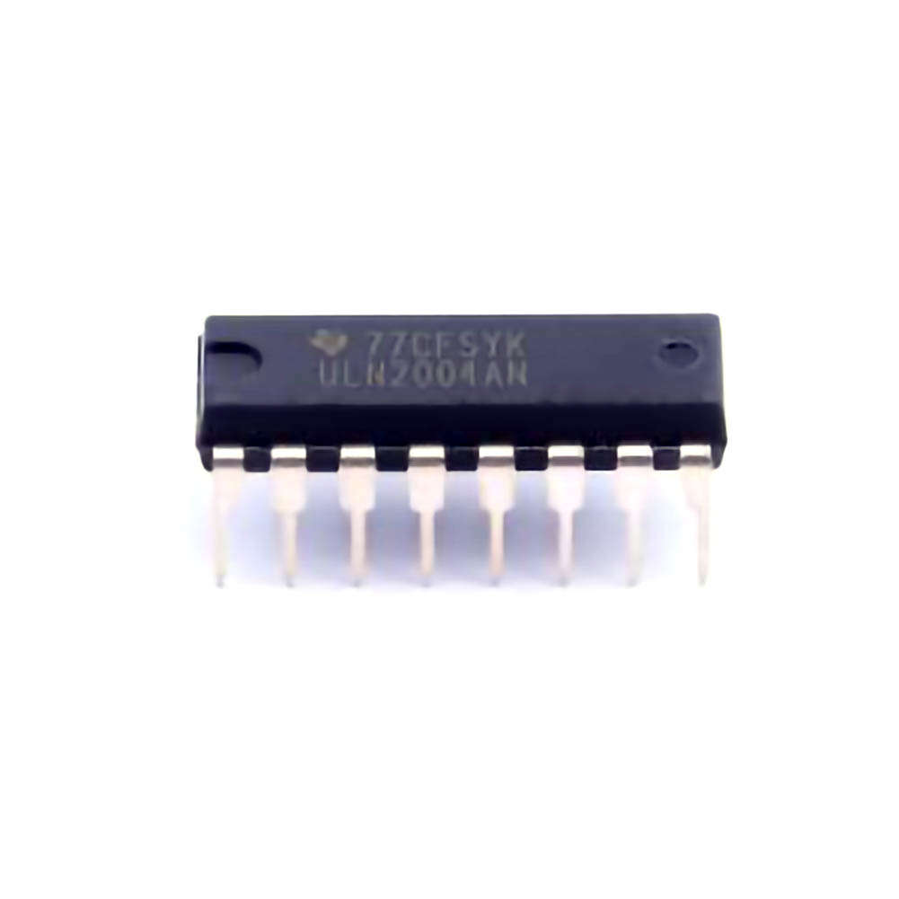
Understanding the ULN2004AN and Common Issues
The ULN2004AN is a high-voltage, high-current Darlington transistor array, often used in applications such as relay drivers, stepper motor controllers, and LED driving circuits. It provides a simple and efficient way to interface low-voltage logic circuits with high- Power loads, making it an essential component in many embedded systems and industrial applications.
While the ULN2004AN is a reliable component, various issues can arise during its use, particularly in complex circuits. Understanding these common issues and their solutions can help improve the reliability and efficiency of your electronic systems. This article provides insights into troubleshooting techniques for common problems encountered with the ULN2004AN.
1. Overheating of the ULN2004AN
One of the most common issues with the ULN2004AN is overheating. The IC is designed to handle high currents and voltages, but if the power dissipation exceeds the recommended limits, it can overheat, causing potential damage or failure.
Causes of Overheating:
Excessive Load Current: If the current drawn by the connected load exceeds the maximum rating of the IC (500mA per channel), the IC may overheat. This can happen if the load is miscalculated or the system is not designed to handle high currents.
Inadequate Cooling: Insufficient heat sinking or poor ventilation around the ULN2004AN can result in heat buildup, leading to temperature rise.
High Ambient Temperature: Operating the IC in environments with high ambient temperatures can also contribute to overheating if the proper thermal Management steps are not taken.
Solutions to Prevent Overheating:
Check Load Ratings: Ensure that the load connected to each channel does not exceed the 500mA maximum current rating. If necessary, use external power transistors to handle higher currents.
Improve Ventilation and Cooling: Install heat sinks or use active cooling (such as fans) in the system to dissipate heat efficiently. Make sure there is adequate airflow around the IC to prevent heat accumulation.
Consider Power Dissipation: Calculate the power dissipation in the IC to ensure it operates within the recommended thermal limits. The power dissipation can be calculated using the formula ( P = I^2 \times R ), where ( I ) is the load current and ( R ) is the on-resistance of the transistors.
Choose a Suitable Ambient Temperature Range: Operate the IC in an environment with a temperature within the recommended range, typically between -40°C to 85°C.
2. Incorrect Logic Level or Input Signals
The ULN2004AN is a Darlington transistor array, meaning it responds to input signals from a logic-level circuit. If the input signal is not within the specified voltage range, the IC may not operate correctly.
Causes of Incorrect Logic Levels:
Insufficient Input Voltage: If the input signal voltage is too low, the transistor array may not fully switch on, leading to incomplete operation.
High Input Voltage: On the other hand, if the input voltage exceeds the maximum rating (typically 5V for TTL logic), it could damage the IC or cause it to malfunction.
Pulse Timing Issues: When driving stepper motors or other time-sensitive components, incorrect pulse timing could result in erratic behavior or poor performance.
Solutions for Logic Level Issues:
Ensure Proper Voltage Levels: Double-check that the input signals are within the recommended voltage range (usually 2.4V to 5V for TTL logic). For lower logic levels, a level shifter or logic buffer can be used to bring the signal into the proper range.
Use Debouncing for Switch Inputs: If you’re using mechanical switches to control the ULN2004AN inputs, ensure that switch debouncing is implemented. This will prevent multiple triggering from switch bounce, which can cause erratic behavior.
Verify Timing Parameters: If the IC is part of a pulse-driven system, ensure that the timing of the input pulses is synchronized with the desired output. This is especially critical when using the ULN2004AN for motor control or driving multiple relays.
3. Overvoltage Protection Failure
The ULN2004AN features built-in flyback Diodes designed to protect the IC from voltage spikes caused by inductive loads, such as motors and relays. However, in some cases, these Diode s may not provide sufficient protection, or the protection circuitry may be inadequate.
Causes of Overvoltage Issues:
Inductive Kickback: When switching off an inductive load (e.g., a relay or motor), the collapsing magnetic field can generate a high voltage spike that may exceed the voltage rating of the ULN2004AN.
Faulty Flyback Diodes: The internal flyback diodes may be damaged or insufficiently rated for the specific inductive load being driven.
Solutions for Overvoltage Protection:
Use External Flyback Diodes: In high-current inductive load applications, it’s advisable to use external flyback diodes (typically 1N4007 or similar) across the load to provide additional protection against voltage spikes.
Use Snubber Circuits: For highly inductive loads, a snubber circuit (a resistor- capacitor network) can be added to suppress voltage spikes effectively.
Ensure Proper Load Ratings: Make sure that the relay or motor connected to the ULN2004AN does not generate voltage spikes that exceed the IC's maximum voltage rating. If necessary, use components rated for higher voltages.
Advanced Troubleshooting and Solutions
4. Signal Integrity Issues
Signal integrity can be an issue when using the ULN2004AN in complex or high-speed circuits. Poor signal quality can lead to unpredictable behavior or loss of control over the connected load.
Causes of Signal Integrity Issues:
Noise in the Input Signals: High-frequency noise or cross-talk from other parts of the circuit can interfere with the logic-level inputs, causing false triggering or erratic switching.
Long Signal Wires: Long connecting wires or traces can introduce parasitic capacitance or inductance, leading to signal degradation.
Grounding Problems: A poor ground connection can cause voltage fluctuations that affect the IC's ability to operate reliably.
Solutions for Signal Integrity:
Use Decoupling Capacitors : Place decoupling capacitors (typically 0.1µF ceramic capacitors) close to the power pins of the ULN2004AN to filter out high-frequency noise.
Shorten Wires and Use Proper Traces: Keep the input signal wires and PCB traces as short as possible to minimize the effects of parasitic inductance and capacitance.
Improve Grounding: Ensure that all ground connections are low impedance and properly connected. Using a star grounding system can reduce noise and ground bounce, improving the overall performance of the circuit.
5. Circuit Layout and Component Placement
The physical layout of the circuit can have a significant impact on the performance of the ULN2004AN. A poorly designed PCB or improper component placement can lead to issues such as overheating, noise, or instability.
Causes of Poor Layout:
Inadequate Trace Widths: If the PCB traces carrying high current are too thin, they can cause excessive voltage drops and heating.
Improper Component Placement: Placing components too close together can lead to overheating and interference. Additionally, if power and signal traces are routed too close, they can introduce noise into the system.
Lack of Thermal Management : Without proper thermal management, the IC may overheat and experience thermal failure.
Solutions for Better Circuit Layout:
Use Proper Trace Widths: Use PCB design tools to ensure that traces carrying high currents are thick enough to handle the load without excessive heating. Online calculators can help determine the optimal trace width.
Optimize Component Placement: Place components in a way that minimizes interference and ensures efficient heat dissipation. High-power components should be placed away from sensitive signal circuits.
Incorporate Thermal Management: Use thermal vias, copper pours, and heat sinks to improve the thermal performance of the PCB. Ensure that the ULN2004AN has sufficient space for heat dissipation.
6. Component Failure Diagnosis
In some cases, the ULN2004AN itself may fail due to manufacturing defects, electrical overstress, or improper handling.
Signs of Component Failure:
No Output Response: If the IC fails to drive the load, it may indicate internal damage.
Excessive Heat: If the IC is heating up without a corresponding load, it may have an internal short or other faults.
Erratic Behavior: If the outputs are fluctuating or not responding to input changes as expected, the IC may be partially damaged.
Solutions for Diagnosing Failures:
Test the IC: Use a multimeter to check for shorts between pins, especially between the ground pin and other output pins. If shorts are detected, the IC may need to be replaced.
Replace the IC: If the IC is found to be faulty, replace it with a new one and test the circuit again. Always use ESD-safe handling procedures when dealing with sensitive components.
Check Surrounding Components: If the IC is operating improperly, inspect surrounding components for failure, including resistors, capacitors, and transistors.
Conclusion:
The ULN2004AN is a highly useful component in a wide range of electronic applications, but it is not immune to issues that can affect its performance. By understanding common troubleshooting strategies—such as preventing overheating, ensuring proper logic levels, protecting against overvoltage, and optimizing circuit layout—you can ensure the reliable operation of this IC in your projects. Keep in mind that a proactive approach to circuit design, component selection, and testing will minimize the likelihood of problems and help ensure the longevity of your electronics.
If you are looking for more information on commonly used Electronic Components Models or about Electronic Components Product Catalog datasheets, compile all purchasing and CAD information into one place.
Partnering with an electronic components supplier sets your team up for success, ensuring the design, production, and procurement processes are quality and error-free.


