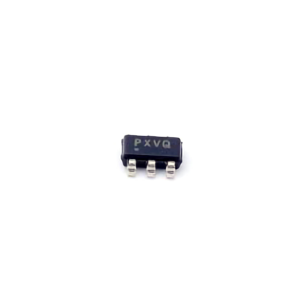
Understanding the TPS3700DDCR and Common Issues
The TPS3700DDCR is a voltage supervisor, designed to monitor the Power rails in a system and provide essential reset signals. Its role is crucial in ensuring that systems power up correctly, stay operational, and shut down properly when needed. However, as with any sophisticated component, troubleshooting and resolving issues is part of the development process.
Before diving into troubleshooting solutions, let’s take a brief look at the TPS3700DDCR’s core functionalities. This device monitors multiple power rails, detects undervoltage conditions, and ensures system stability by issuing reset signals when necessary. These resets are essential for protecting sensitive components, preventing erratic behavior, and ensuring reliable performance across a wide range of applications.
Key Features of the TPS3700DDCR
Multiple Voltage Monitoring: The TPS3700DDCR can monitor multiple voltage inputs, making it ideal for systems with complex power requirements.
Low Power Consumption: This device consumes minimal power during operation, which is a crucial feature for battery-powered systems and energy-efficient designs.
Wide Input Voltage Range: It supports a broad input voltage range from 1.2V to 5.5V, making it highly versatile for various system designs.
Precision Reset Thresholds: With its adjustable threshold settings, the TPS3700DDCR allows for fine-tuned voltage monitoring, offering flexibility for different power rail requirements.
Active Low Reset Output: The reset output is active low, indicating when the monitored voltage has fallen below the threshold.
Common Issues with the TPS3700DDCR
Despite its reliability, engineers and technicians may encounter certain issues when integrating the TPS3700DDCR into a system. Below are some common problems:
Incorrect Reset Behavior:
One of the most frequent issues with the TPS3700DDCR is incorrect reset behavior. This issue may manifest as the device issuing a reset when it shouldn’t, or failing to issue a reset when it should.
Possible Causes:
Incorrect threshold settings: The voltage threshold might not be configured correctly for the system’s requirements.
Power supply instability: If the power supply is noisy or unstable, the voltage monitoring could trigger false resets.
Improper wiring or layout: Incorrect PCB layout or wiring can cause the reset line to behave unpredictably.
Solution:
Double-check the threshold configuration: Ensure the voltage threshold is set to the correct value for your application. You can adjust the threshold using external resistors to fine-tune the settings.
Clean up the power supply: Use proper decoupling capacitor s and ensure the power supply is stable. Any noise or ripple in the supply voltage can lead to false resets.
Check the reset line routing: Ensure the reset line is not subject to noise or interference. Keep the reset line short and away from high-speed signal traces to reduce susceptibility to unwanted resets.
Excessive Power Consumption:
The TPS3700DDCR is designed for low power consumption, but in some systems, users may notice higher than expected current draw.
Possible Causes:
Inadequate power-down mode: If the power-down mode is not correctly implemented, the device may continue drawing power even when the system is off or in a low-power state.
External components: Additional components connected to the reset line or power input may be drawing excess current.
Solution:
Verify power-down logic: Ensure that the power-down functionality is correctly configured in your design. This may include using the appropriate shutdown pins or enabling power-down modes in your system to reduce power consumption during idle periods.
Review external components: Check whether any components connected to the TPS3700DDCR are drawing more current than expected, and ensure that they are compatible with the power requirements of the supervisor IC.
Reset Pulse Timing Issues:
In some applications, the timing of the reset pulse is critical. If the TPS3700DDCR does not issue the reset pulse at the right time, it can cause system instability or malfunction.
Possible Causes:
Incorrect threshold detection delay: If the reset threshold detection delay is too short or too long, the system may either reset too early or too late.
Signal propagation delay: The PCB layout and wiring can introduce delays in the signal propagation, which can affect the timing of the reset pulse.
Solution:
Adjust delay settings: Some versions of the TPS3700DDCR provide an adjustable delay on the reset signal. Check the datasheet for specific recommendations on setting the delay to ensure it matches the timing requirements of your system.
Optimize PCB layout: Make sure the reset signal routing is as direct and short as possible to minimize signal delays. Additionally, consider using buffer stages or signal amplifiers to drive the reset pulse more reliably.
False Reset Triggers:
False resets, where the device triggers a reset when no real undervoltage condition exists, can be a frustrating issue. This may happen if the TPS3700DDCR detects noise or fluctuations in the monitored voltage rails.
Possible Causes:
Input voltage noise: Any fluctuation or noise on the power rails can cause the TPS3700DDCR to mistakenly register an undervoltage condition.
Incorrect threshold voltage: If the threshold voltage is set too close to the actual operating voltage of the power rail, small variations can trigger false resets.
Solution:
Improve power filtering: Use proper bypass and decoupling capacitors to filter out noise from the power rails. Ensure that the capacitors have the correct values for the frequency ranges likely to be encountered.
Set appropriate thresholds: Ensure that the voltage threshold is set to a level that accounts for typical voltage variations in the system. Avoid setting the threshold too close to the nominal voltage value.
Inadequate Reset Duration:
The duration of the reset pulse may not be long enough to allow the rest of the system to react before it begins operating again. This can be especially problematic in systems where the reset line needs to propagate to multiple components or circuits.
Possible Causes:
Insufficient reset pulse width: The default reset pulse width might not be sufficient for the system’s needs.
External components: Some external components connected to the reset line may require a longer pulse width to function correctly.
Solution:
Adjust reset pulse width: Check the datasheet for the TPS3700DDCR for options to extend the reset pulse width. In some cases, adding an external capacitor to the reset pin can help extend the duration.
Review system requirements: Ensure that the reset duration meets the requirements of all the components in the system. If necessary, use external timing components like capacitors or resistors to modify the pulse width.
Advanced Troubleshooting and Optimization of the TPS3700DDCR
In the second part of this guide, we will dive deeper into advanced troubleshooting techniques and optimization strategies for the TPS3700DDCR. By addressing the more complex issues that may arise in demanding applications, we can ensure that the voltage supervisor continues to perform optimally.
Advanced Troubleshooting Techniques
Temperature Sensitivity and Thermal Management :
The TPS3700DDCR, like most integrated circuits, is susceptible to temperature variations. If the device operates in an environment where temperature fluctuates widely, it may exhibit unexpected behavior, such as false resets or delayed responses.
Possible Causes:
Overheating: The device might be operating outside its recommended temperature range, leading to instability.
Temperature-induced threshold shifts: Temperature changes can cause the internal voltage thresholds to shift, which might result in incorrect resets.
Solution:
Ensure adequate cooling: If your system operates in a high-temperature environment, ensure proper heat dissipation for the TPS3700DDCR and other components. Consider adding heat sinks or using active cooling methods if necessary.
Use temperature-compensated components: Some components, like resistors, may experience significant shifts in resistance with temperature changes. Choose temperature-compensated resistors or other components for critical applications.
Integrating the TPS3700DDCR with Complex Power Systems:
In systems with multiple power domains or complex power management circuits, ensuring proper integration of the TPS3700DDCR can be challenging.
Possible Causes:
Power sequencing issues: In systems with multiple voltage rails, incorrect sequencing or timing of power-up/down can lead to unexpected reset behavior.
Cross-domain reset signals: If the reset signals are not correctly managed across different power domains, components may reset at inappropriate times.
Solution:
Implement power sequencing: Use dedicated power sequencing ICs or carefully manage power-up/down events to ensure that all voltage rails are stable before the system begins operating.
Use cross-domain reset management: In multi-rail systems, use level shifters or reset supervisors to propagate the reset signal appropriately across all domains.
System-Level Debugging Using an Oscilloscope:
When troubleshooting the TPS3700DDCR, an oscilloscope can be an invaluable tool for visualizing the voltage levels and reset signal behavior.
Possible Causes:
Oscilloscope usage: Incorrect probe placement or improper use of the oscilloscope can lead to misinterpretation of the results.
Solution:
Use the oscilloscope to monitor the voltage levels at the input pins and reset output. Check for clean transitions, stable voltage readings, and proper reset signal timing.
Ensure that you probe the reset line directly at the TPS3700DDCR pin to avoid signal degradation or noise pickup from long wires.
Final Optimization Strategies:
After troubleshooting the TPS3700DDCR and addressing potential issues, consider optimizing the device for performance in your application.
Optimization Tips:
Minimize the number of components connected to the reset line to reduce the chances of signal degradation.
Use low ESR capacitors for power filtering to enhance noise suppression.
Consider using external logic for more complex reset timing or behavior requirements.
Conclusion:
Troubleshooting and optimizing the TPS3700DDCR voltage supervisor is a crucial skill for engineers and technicians working on power management systems. By understanding the common issues and implementing the solutions provided in this article, you can ensure that your system runs reliably and efficiently. Always start by verifying the fundamental configuration of the device, and use advanced techniques like thermal management, power sequencing, and signal monitoring to address more complex challenges. By taking these steps, you can achieve optimal performance and long-term reliability in your design.
If you are looking for more information on commonly used Electronic Components Models or about Electronic Components Product Catalog datasheets, compile all purchasing and CAD information into one place.
Partnering with an electronic components supplier sets your team up for success, ensuring the design, production, and procurement processes are quality and error-free.


